 Books
Books Technology
 Electronics
 Programming
 Web-interface
 Graphical interface
 Windowed Application
 Video
Video Images
 Audio
Audio Text
Text HTML
HTML Lof-files
 Neural networks
 All tags
 Weaponry
 Arduino
 Projects
Connecting peripherals, expansion boards
Article-series: Programming Arduino from scratch #2
The controller communicates with the outside world using digital and analog inputs - the same contacts along the perimeter of the board to which a certain voltage can be supplied by the controller or externally.
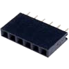 It happens that, to save money or for another reason, the controller board comes without them - Just drill holes in the right place. Then the wires will have to be soldered to the board directly, or you can buy connectors with the appropriate number of contacts. Arduino uses 2.54mm pitch pin headers. If you need to buy them separately, then look for PBS or PBD connectors (for one or two rows of pins). But in this case, you can’t do without minimal knowledge of soldering, so it’s better for a very green beginner to buy a board with already soldered connectors
The contacts can be connected using pin connectors, i.e. There is no need to solder anything at this stage (which is good news for a novice user). If necessary, the wire can simply be stripped and plugged into the connector, but such a connection will not be reliable, so it is better to use connecting wires with corresponding pins at the ends. Moreover, they often come complete with a controller in so-called “starter kits”
Moreover, connecting a wire with a pin at the end to the corresponding connector is not the only option for connecting the controller to the outside world. Together with the controllers, so-called shields, or, in Russian, expansion boards, are sold. At the bottom of such a board there are contacts, the size and location of which fully corresponds to the position of the corresponding connectors on the controller. 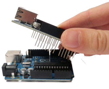 It is enough to place such a board on the controller to get a vertical “sandwich” in which the contacts of the controller and the board are connected to each other by vertical contacts. And all this without using a soldering iron, which is good news for a beginner.
Moreover, many expansion boards do not use all the controller pins, and it is possible to put one or more boards on top. Such a multi-story “sandwich” allows you to connect as many expansion cards to the controller as the corresponding inputs and outputs of the controller are sufficient for. The only thing you need to make sure is that there are no boards that use the same output.