 Books
Books Technology
 Electronics
 DC motors
 Raspberry Pi Controllers
 Relay
Relay Temperature sensors
 Analog sensors
 Digital sensors
 ADC
ADC Bluetooth
 Radio communication 2.4 GHz
 LCD-screen
 All tags
 Programming
 Web-interface
 Graphical interface
 Windowed Application
 Video
Video Images
 Audio
Audio Text
Text HTML
HTML Lof-files
 Neural networks
 Weaponry
 Projects
System for reading an array of analog sensors and display the results matrix
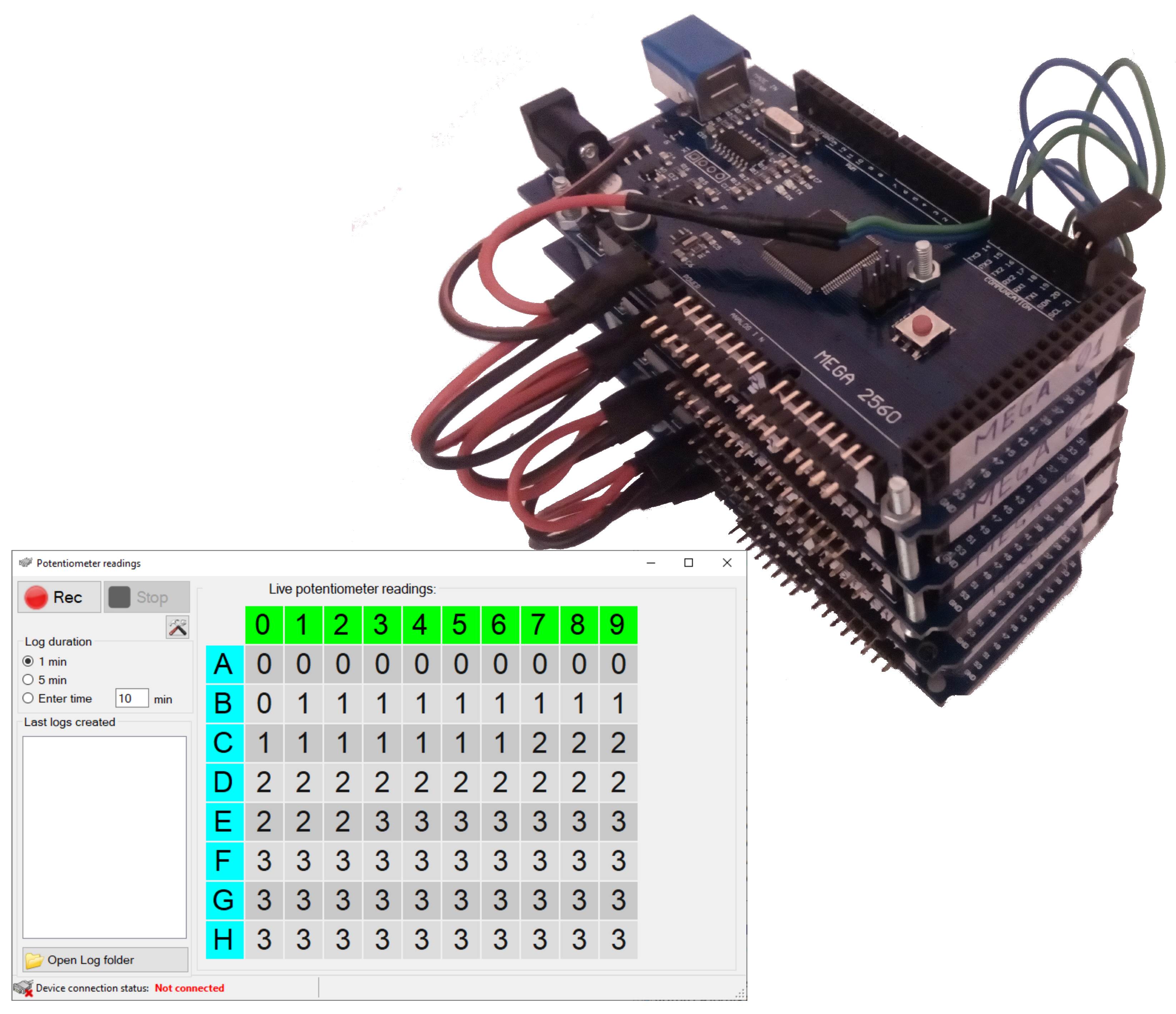
System designed to reading an array of analog sensors and display the results matrix in a convenient form (on a PC screen)
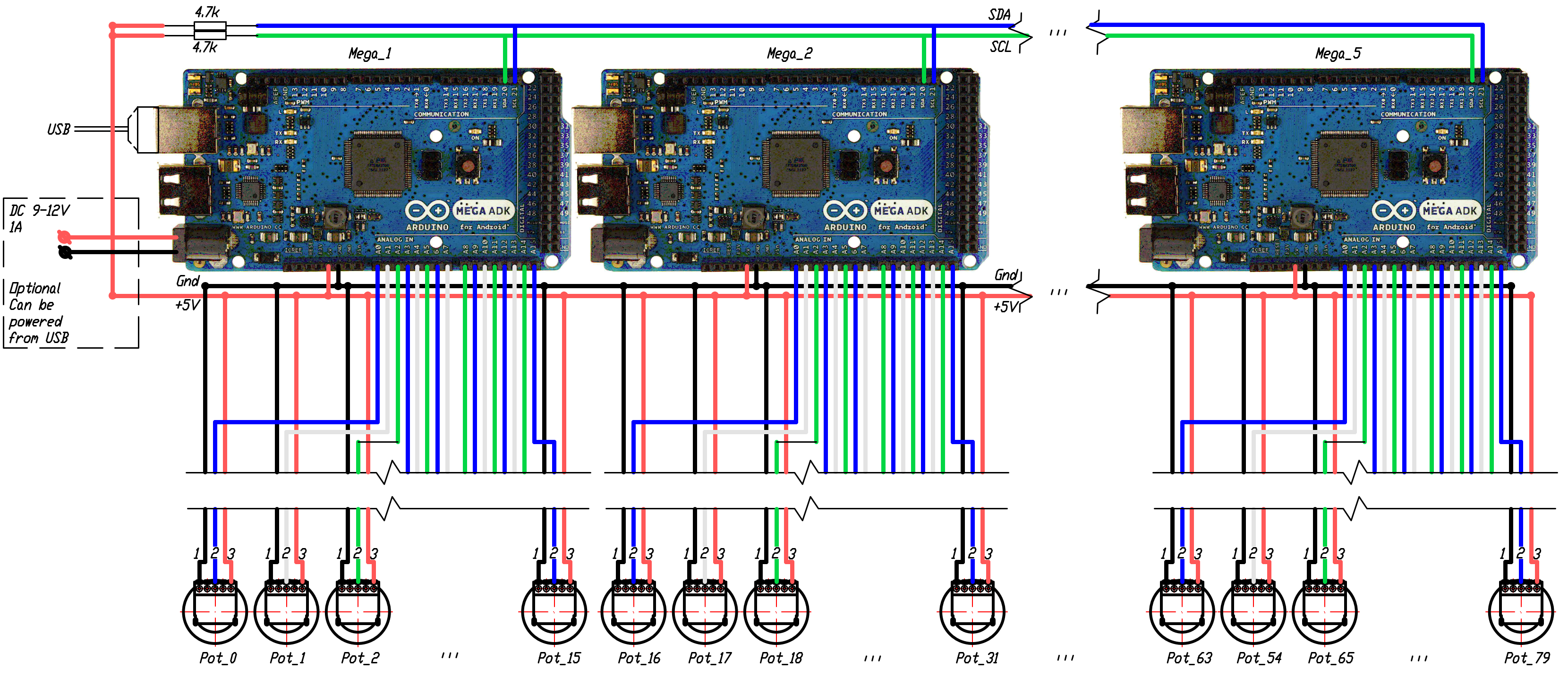
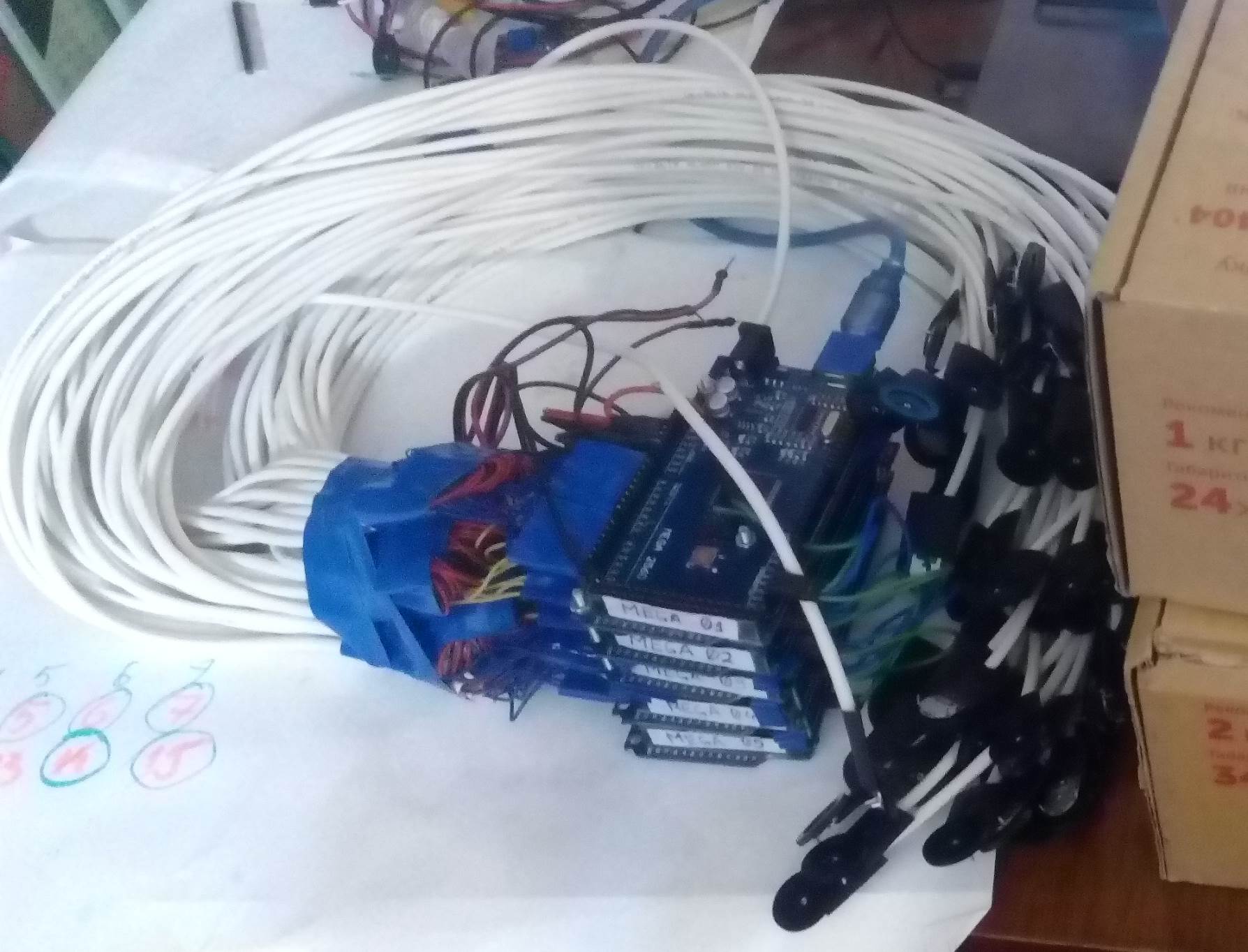
For testing to simulate sensors, disk (“gear”) potentiometers are used, similar to those normally used to adjust volume. The regulators have two extreme positions, to move between which you need to make at least one revolution of the disk. The entire range is divided into sections (adjustable by software). Each sensor is connected to the analog input of the controller. Due to the limitation on the number of analog inputs, several controllers connected in parallel are used. Data transfer between controllers (each supports up to 16 sensorsh) via the I2C protocol.
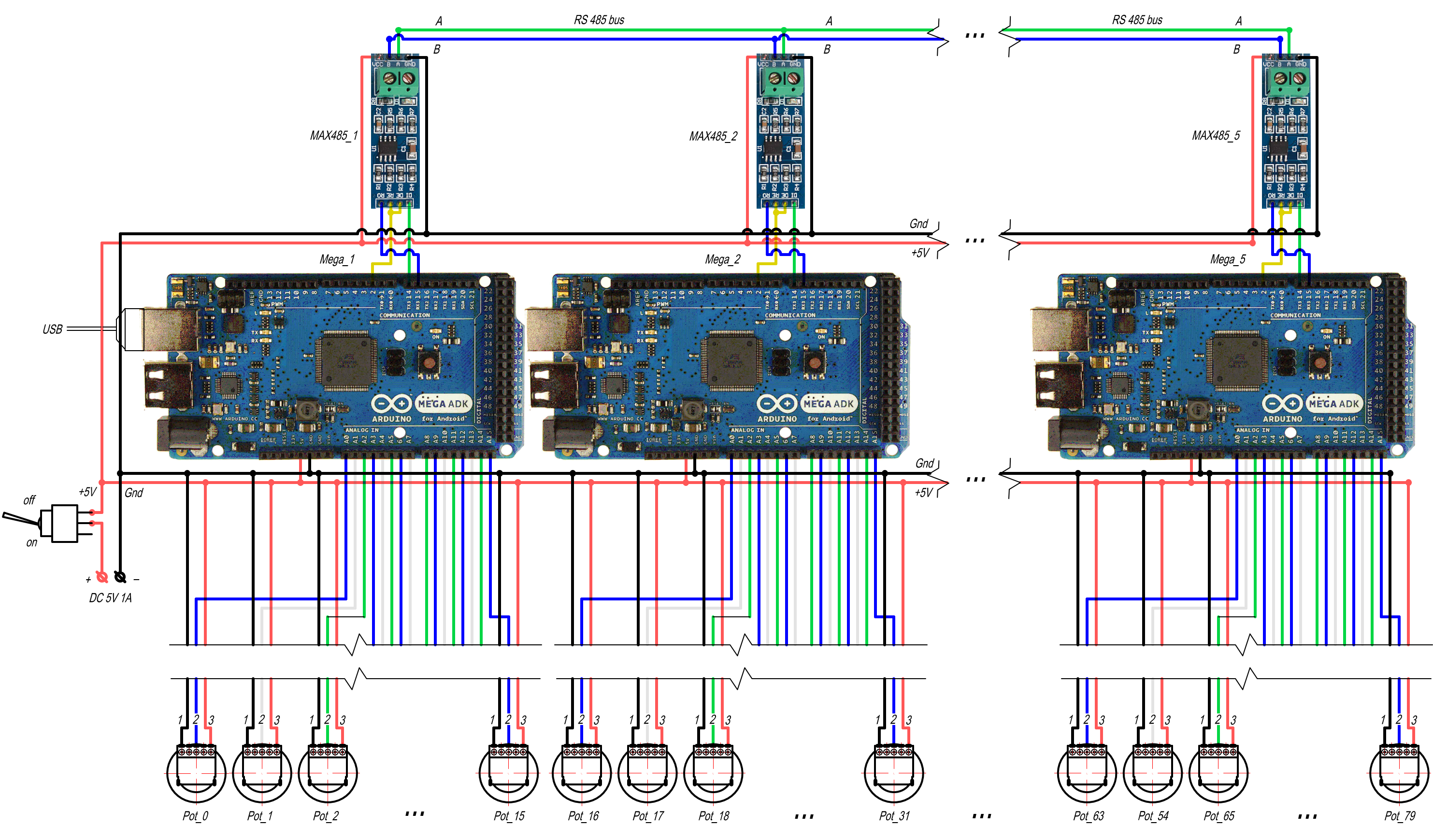
If it is necessary to place sensors over a large area, then the controllers can be connected to each other using the RS-485 interface (from several hundreds meters up to 1,2 km The main controller is connected to the PC via USB (emulates a COM port).
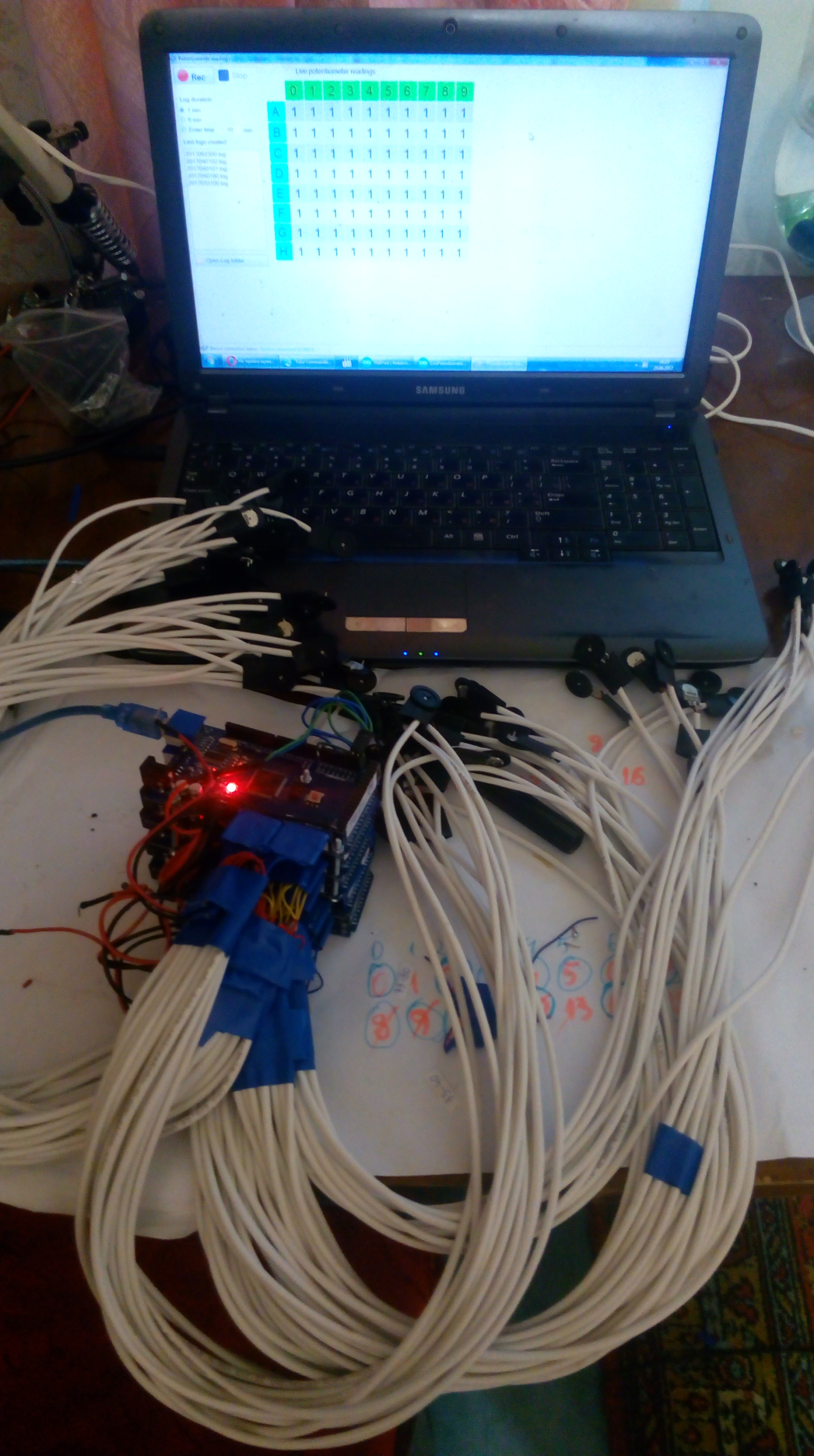
To connect to the controller and display data graphically, use a window application, which in real time displays a matrix with current values for all sensors with the ability to record logs and configure display parameters
System parameters:
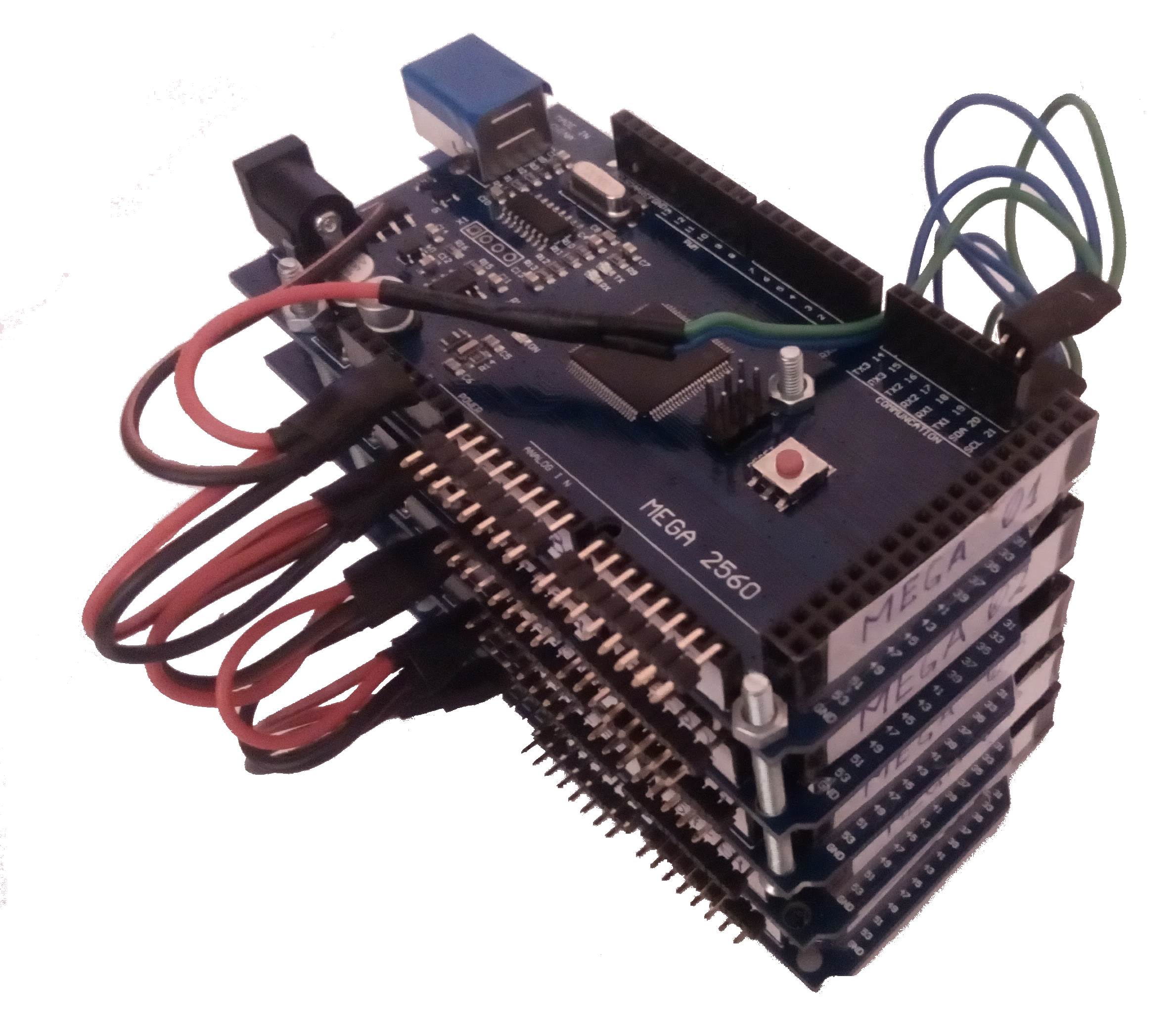
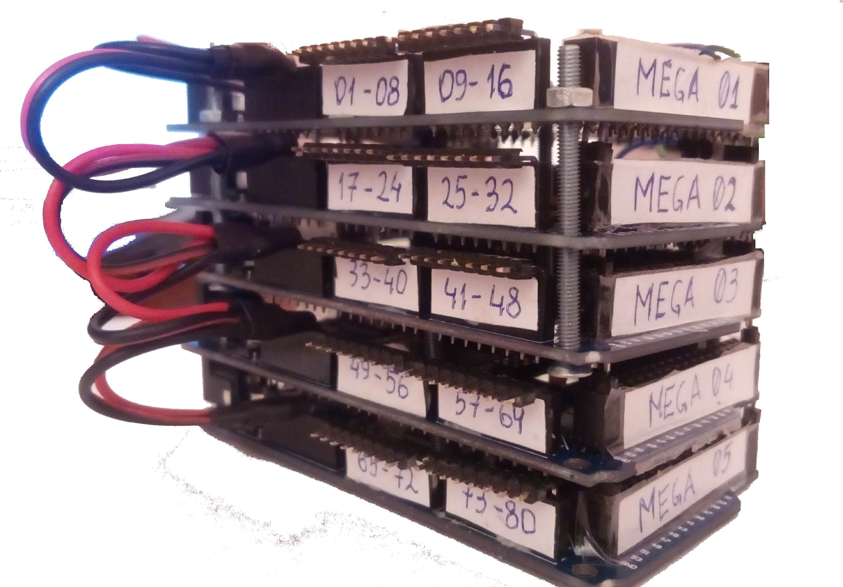
- Main controller – Arduino MEGA – 5pcs.
- Processor – 16 MGh, ATmega2560
- Controller memory – 256kB + 8 kB SRAM+ 4kB EEPROM
- Analog sensors – 80 (5 groups by 16 sensors per each controller)
- Analog input range – 0..5 V
- Analog-to-digital converter – 10bit (1024 levels)
- ADC max resolution – 0.0049 V
- ADC max frequency – 10 kGh
- Max distance between groups of sensors
- up to 20 m (for I2c protocol between controllers)
- up to 1200m (for RS-485 connection between controllers)
- Power supply – 7-12V (possible 5V USB for testing purpose
- Dimensions
- 102x54x50 mm (controllers)
- 240x170x100 mm (whole package with controllers, test potentiometers and wirings)
- Weight
- 250 g (controllers)
- 700 g (whole package with controllers, test potentiometers and wirings)
Applications for displaying sensor values
Desktop application for work of engraving machine. Developed on C++ using .Net framework. Can work on any PC with operating system supporting .NET framework (windows 7,10,11)
[Reading Sensors Array control application](/src/projects/ReadingSensorsArray/ReadingSensorsArray /ReadingSensorsArray.1.1.exe)
Main functions of control application
- Panel for device connection with choose of available ports
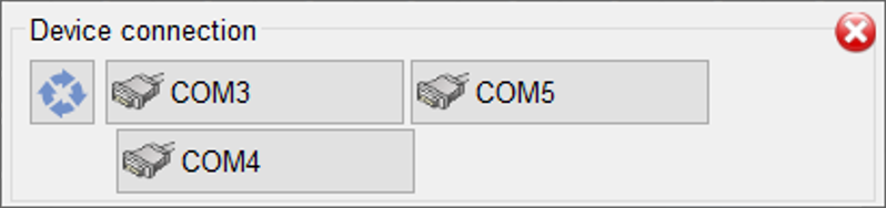
Status of connection with device
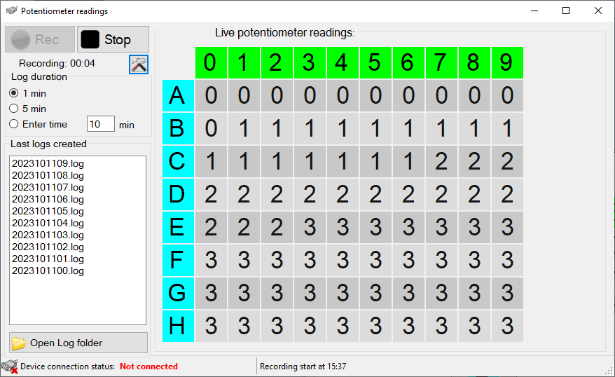
Main window with live sensors readings in form of matrix (10x8)
Start or stop logging process
Change frequency of sensor reading for logging and overall log duration
Display list of last recorded logs and button to show folder where thus logs were saved (by default, the “log” folder is created in the same place where the control application was launched)
Setting display options
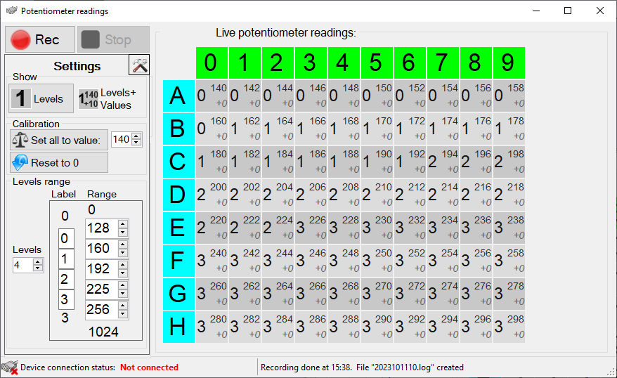
- Displays only the level or also absolute values on the analog sensor
- Manually setting the default value (if any of the sensors is not connected, this value will be displayed for it)
- Changing the number of levels to display
- Setting label for each level (by default, serial numbers are used, but letters or symbols can also be used)
- Setting for each level the range of sensor values that corresponds to it (by default, the entire range is divided into equal sections by the number of levels)
Components
- Controller Arduino MEGA – 5 pcs.
- Disk potenciometer – R1001G21B1 – 80pcs.
- RS-485 module – MAX485 (5 pcs)
Wiring diagram
Possible connection using RS-485
Further development of the system
-
Connection different types of sensors
-
Adding digital sensors connected via I2C or RS485
-
Adding independent screen with control interface for using system without connection to PC
-
Adding special emergency signals for sensors or sensor groups (with audio or light signalization)
-
Improvemets of control application usability
- adding graphs
- opening previously saved logs
- switching and fine tuning of sensor groups and separate sensors
-
Web interface
Photos
https://github.com/Brabn/ReadingSensorsArray/assets/140490234/9c37173d-ba45-4cd9-968d-364d83d57440