Books
Books Technology
 Electronics
 DC motors
 Raspberry Pi Controllers
 Relay
Relay Temperature sensors
 Analog sensors
 Digital sensors
 ADC
ADC Bluetooth
 Radio communication 2.4 GHz
 LCD-screen
 All tags
 Programming
 Web-interface
 Graphical interface
 Windowed Application
 Video
Video Images
 Audio
Audio Text
Text HTML
HTML Lof-files
 Neural networks
 Weaponry
 Projects
Smart glasses with blink detector
Glasses that take photos of the field of view using a blinking sensor and transfer the image to the cloud for further processing
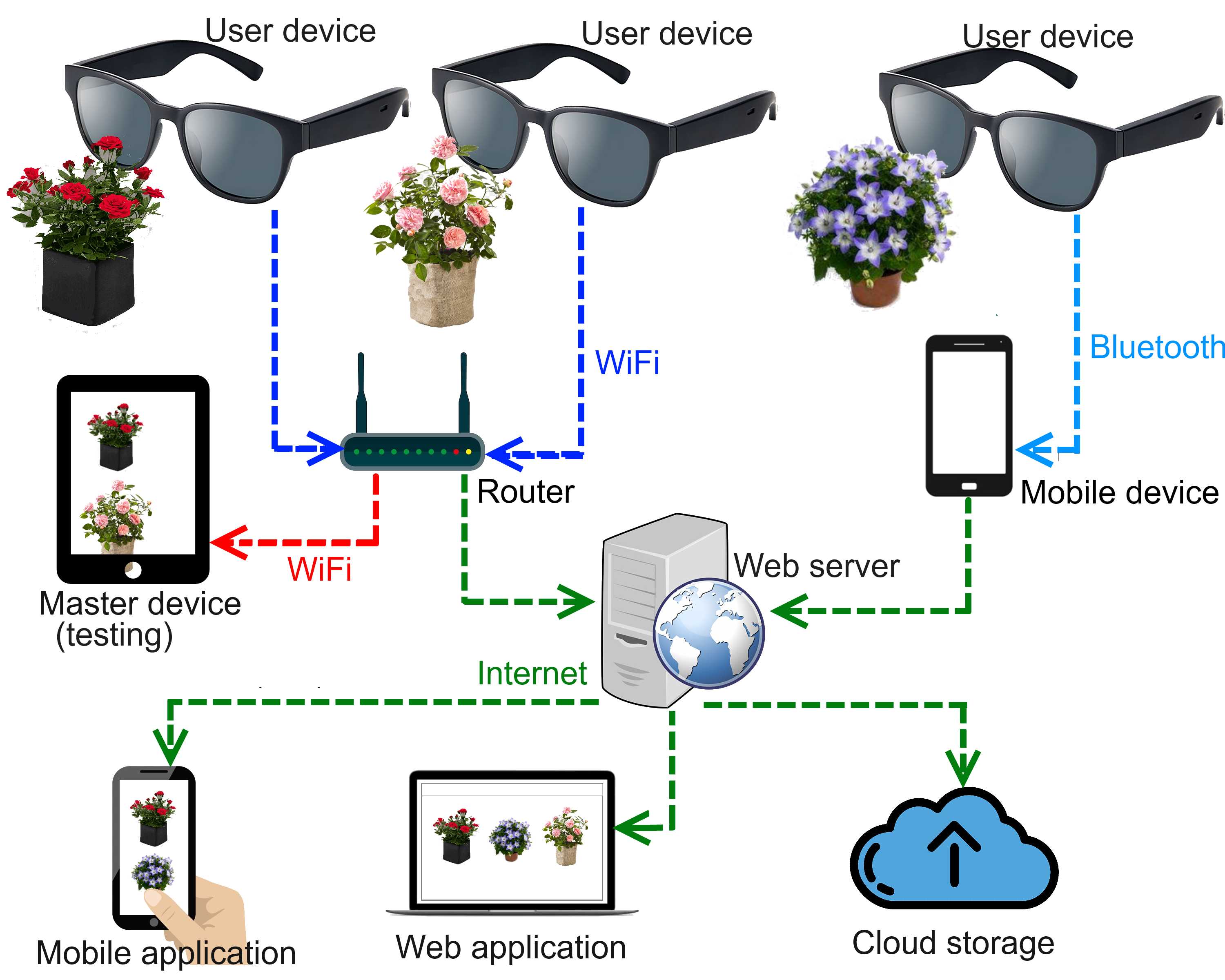
General service description
The system consists of a set of user devices in the form of glasses with a built-in camera and a sensor that detects blinking. User devices connect to the network via Wi-Fi (directly) or Bluetooth (with intermediate mobile device)
When the sensor is triggered (a single blink or a specified set of eyes movement), the user’s field of view is captured and a time stamp with a geotag is sent to the central server. In this case, the photo is saved in the device’s memory, which stores a certain number of recent photos with the corresponding timestamps and geotags. 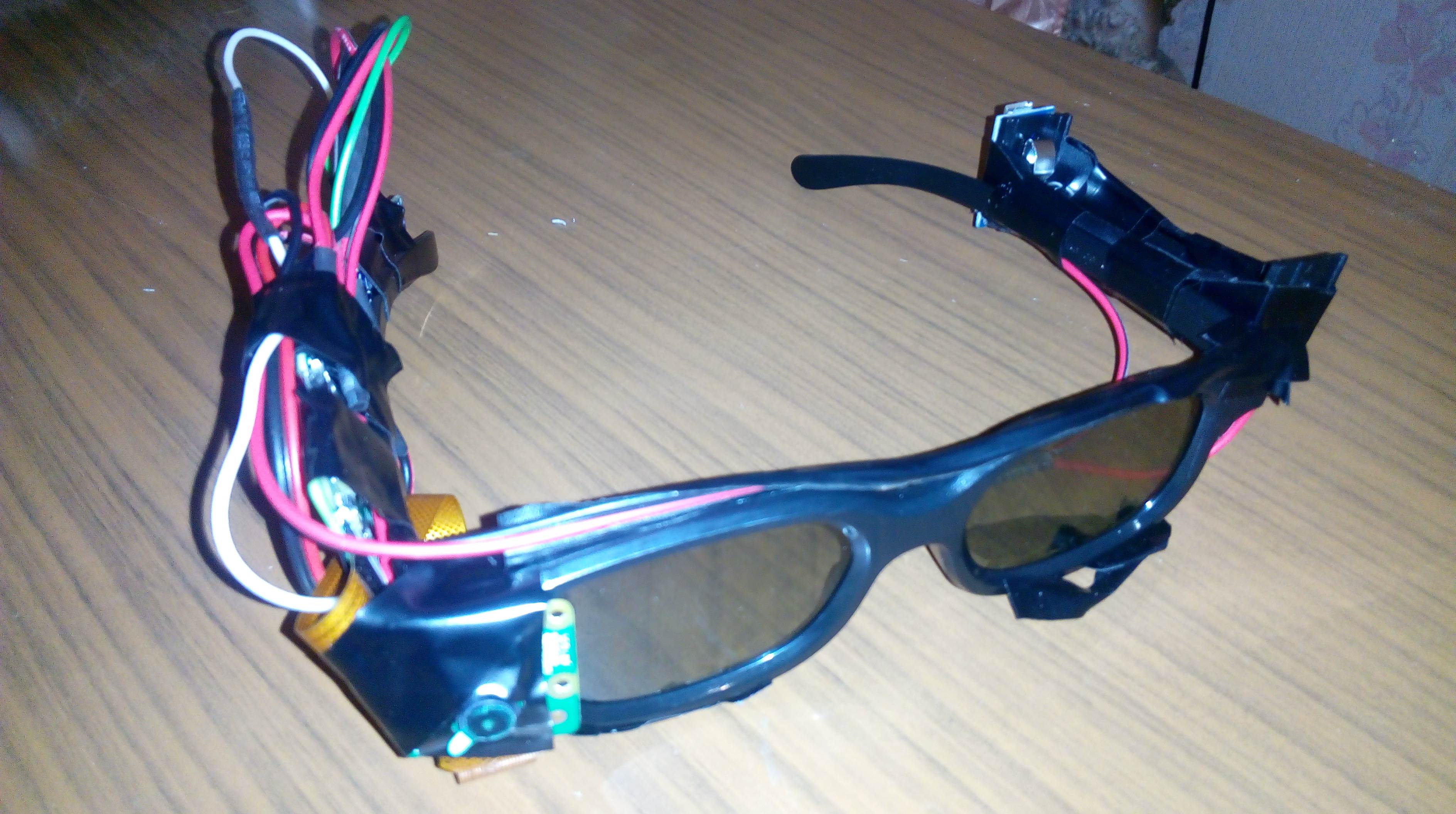 The server part processes data from user devices and determines the filter of interest. The simplest filter is photos from users who are in a certain place and blink at the same time. Filtering options can be configured on the server side or by the service users themselves. After receiving a command from the server, the device sends a photo with the requested timestamp
The photo is processed on the server along with photos of other user devices and saved in the cloud The result can be displayed in the web version or mobile application, in which the user can configure the filtering principle, see their own scores, the most popular ones, etc.
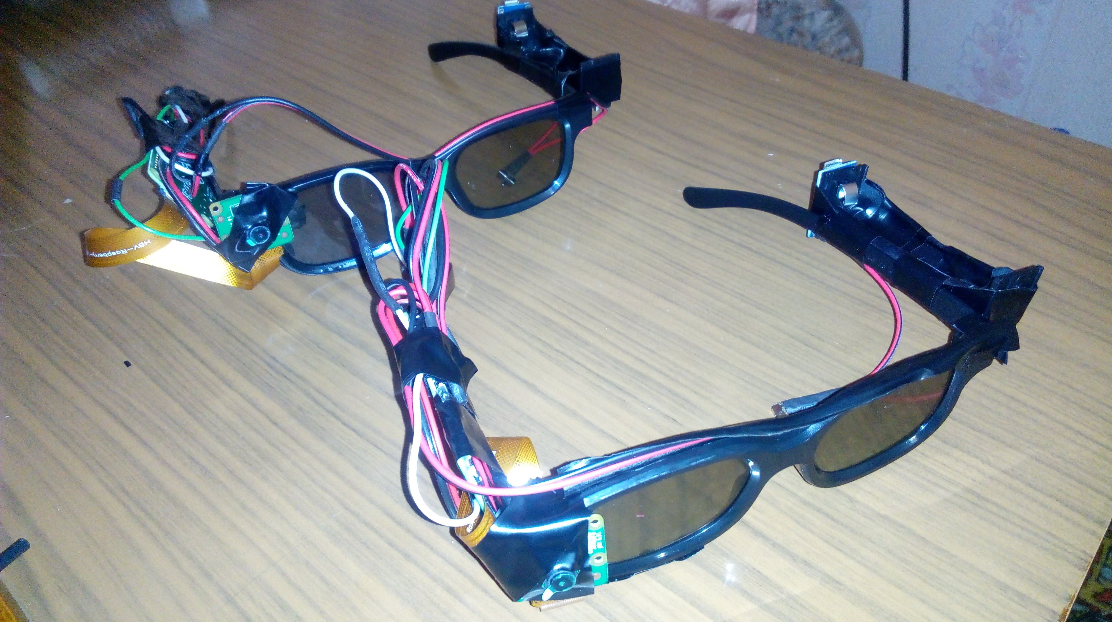
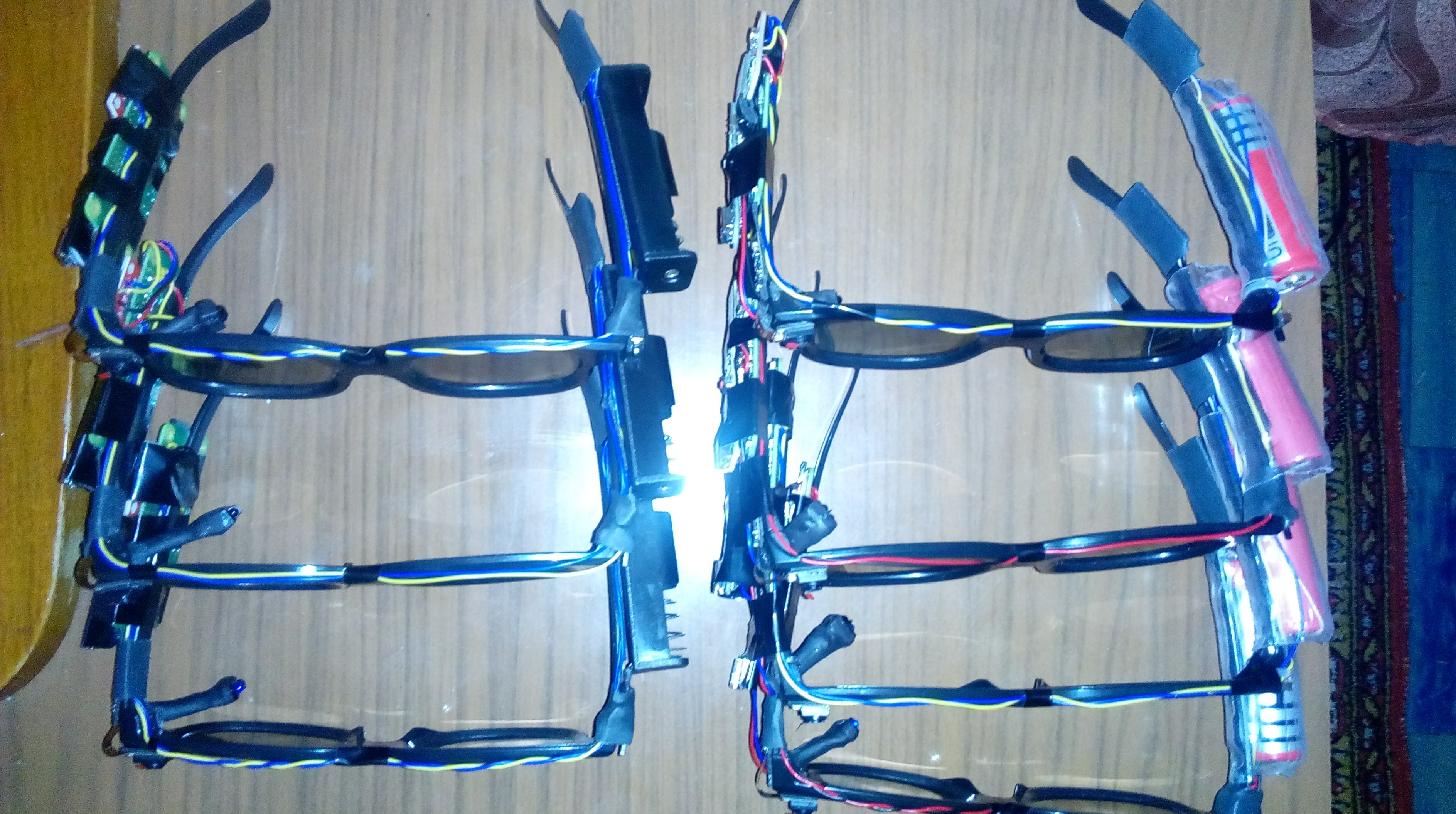
Description of the user device
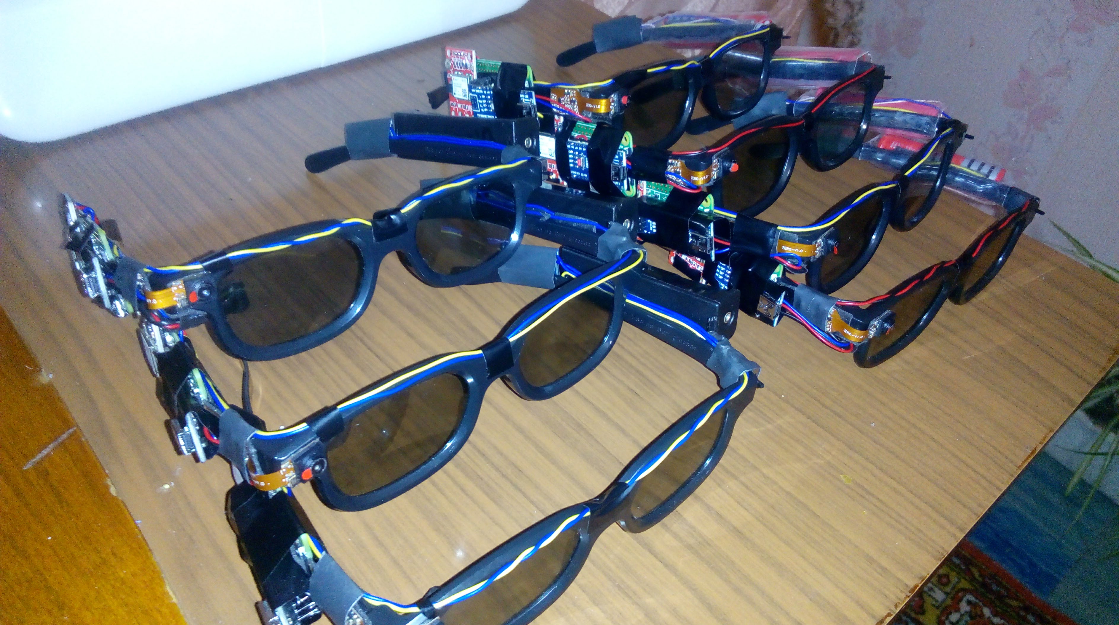
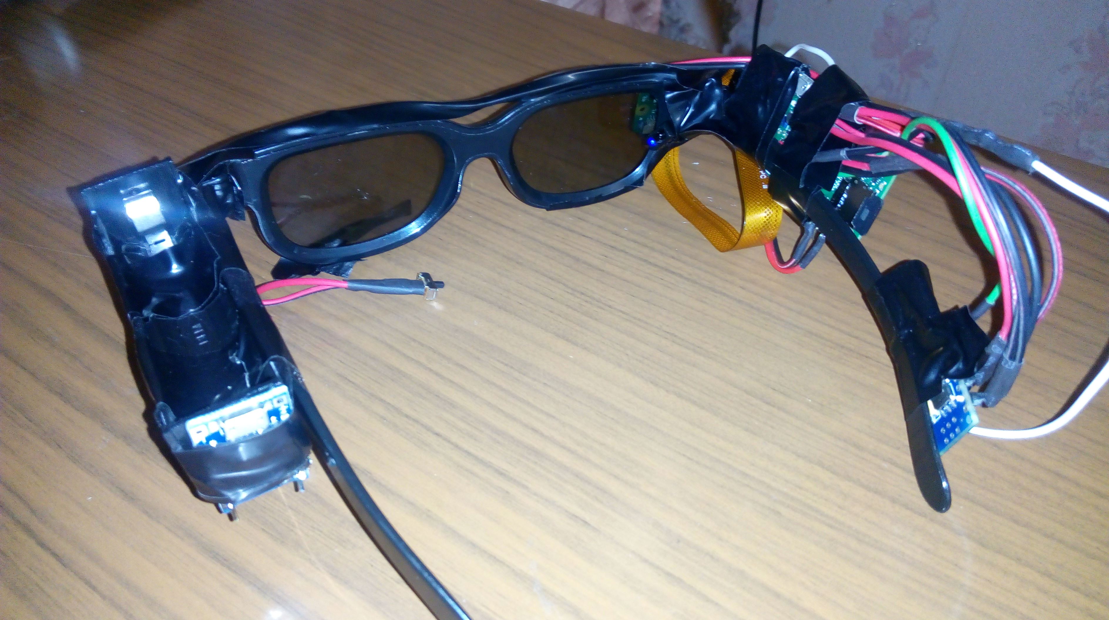
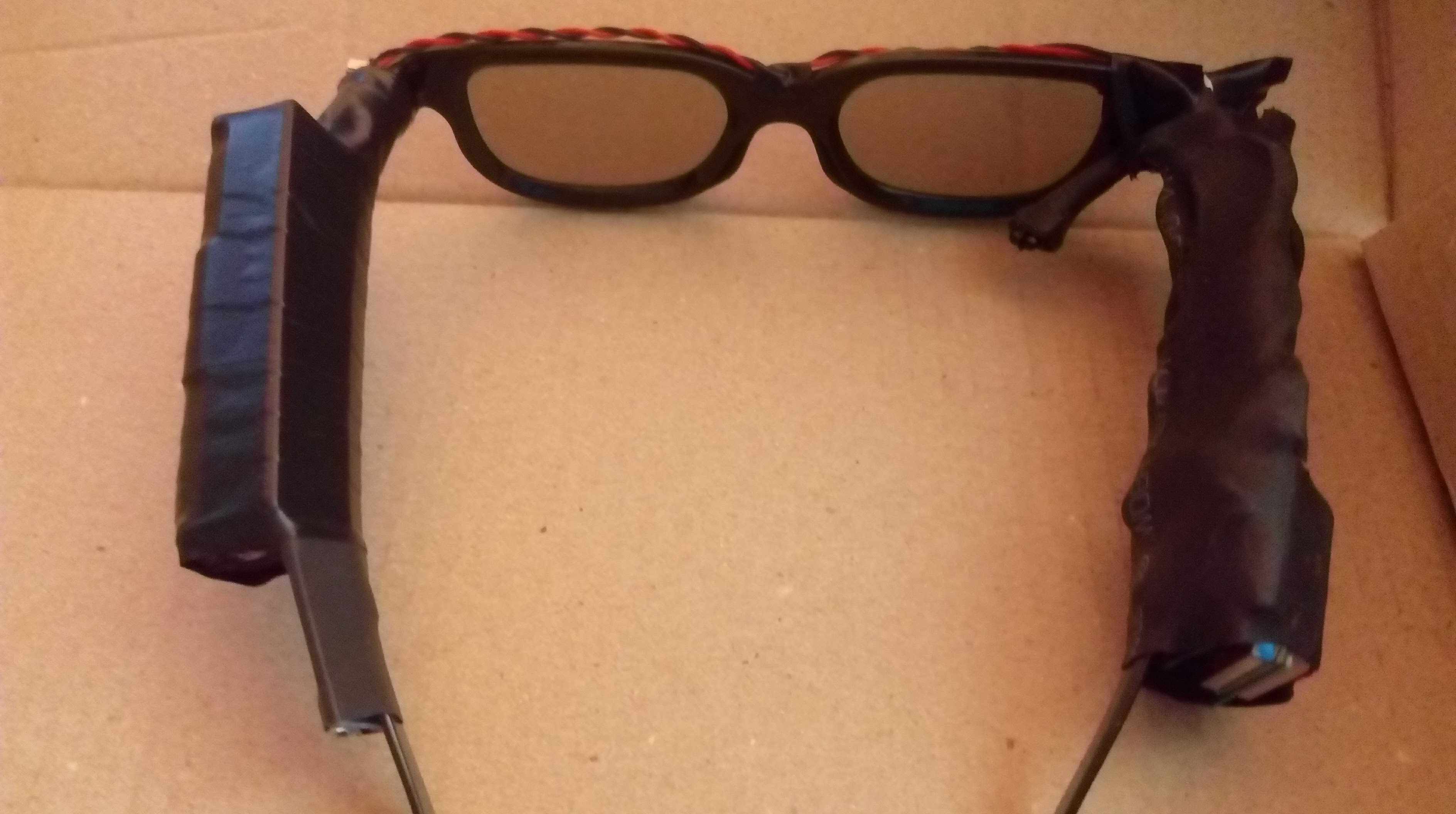
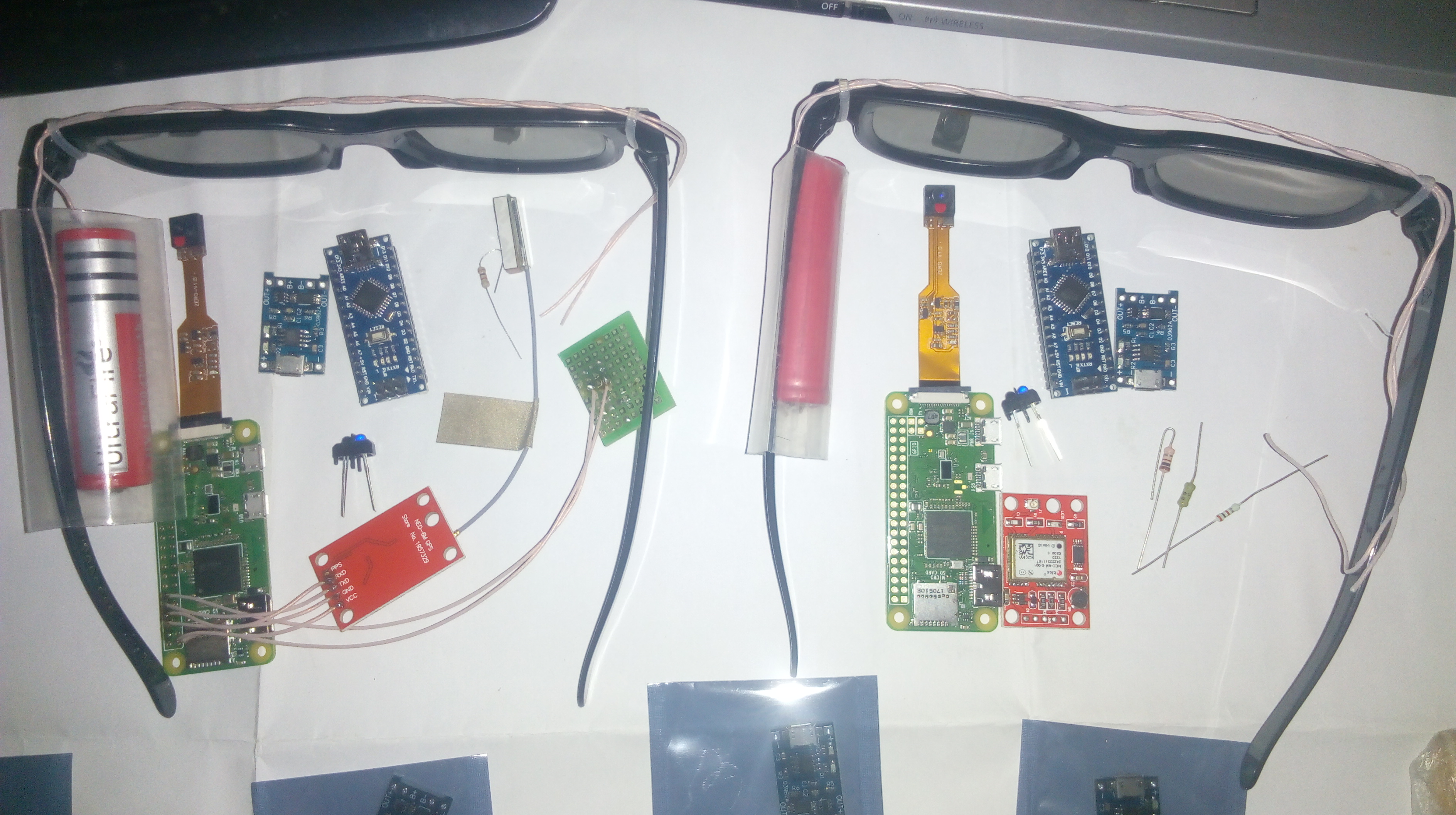
It consists of a frame in the form of glasses (without diopters) on which the remaining components are attached. A camera is mounted on the front that records the user’s field of view. Opposite one of the eyes there is an analog IR sensor aimed at the white of the eye. The sensor is connected to an auxiliary controller (based on Atmega 328P). The signal about the occurrence of this event is transmitted to the main controller (Raspberri Pi Zero). Power is provided by an 18650 battery, which can be charged using the TP4056 charge controller via microUSB port.
Logic of the user device
Blinking is detected by a TCRT5000 analogue IR sensor aimed at the white of the eye. The sensor is connected to the analog input of the auxiliary controller. An open and closed eye gives different indicators, which allows, after processing the signal with a built-in algorithm, to determine the moment of blinking with fairly high accuracy.The logic signal is transmitted to the main controller through pull-down resistors.
The main controller (Raspberri Pi Zero) connects to a WiFi network, which provides an Internet connection. When a flashing command is received, an image is taken from the camera, saved to the memory card and a packet is sent to the IP server along with the device ID The auxiliary controller runs on firmware written in C++, the main controller is a Python script + the main system is based on the Linux kernel
Wiring diagram of User device

“Master” device for testing
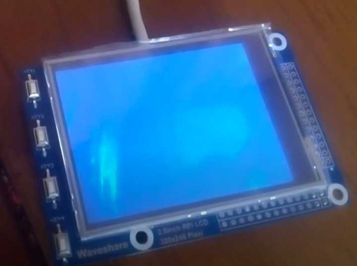
For testing purposes, a test “master” device has also been developed, which emulates some server functions (in particular, requesting photos) and displays them on the built-in screen. The test master device does not require a network connection - by default it works with all devices on the same local network Consists of a Raspberri Pi Zero controller with a connected touch screen and power supply
Logic of the master device (for tests)
The master device emulates the functions of a web server. When you turn on several user devices on the same local network (connected to the same WiFi router), each of them opens a network connection with the master device. The master device records packets with time stamps from each device. If the packets meet a specified criterion (for example, the difference between the moment of blinking on several devices is less than a specified range), a request is sent to the corresponding devices to send a photo. The user device converts the photo into a data set and sends it to the server address. The server stores the image in memory and displays it on the screen.
Main system parameters for User device
- Main controller – Raspberry Pi Zero W
- Main processor – 1 GGh, ARM1176JZ-F
- Graphic processor – VideoCore IV 48+
- Chipset – Broadcom BCM2835
- RAM – 512 Mb DDR2
- Memory – 8 Gb (microSD)
- Communication – WiFi 802.11 b/g/n, Bluetooth 4.1
- Connectors – MicroUSB, miniHDMI
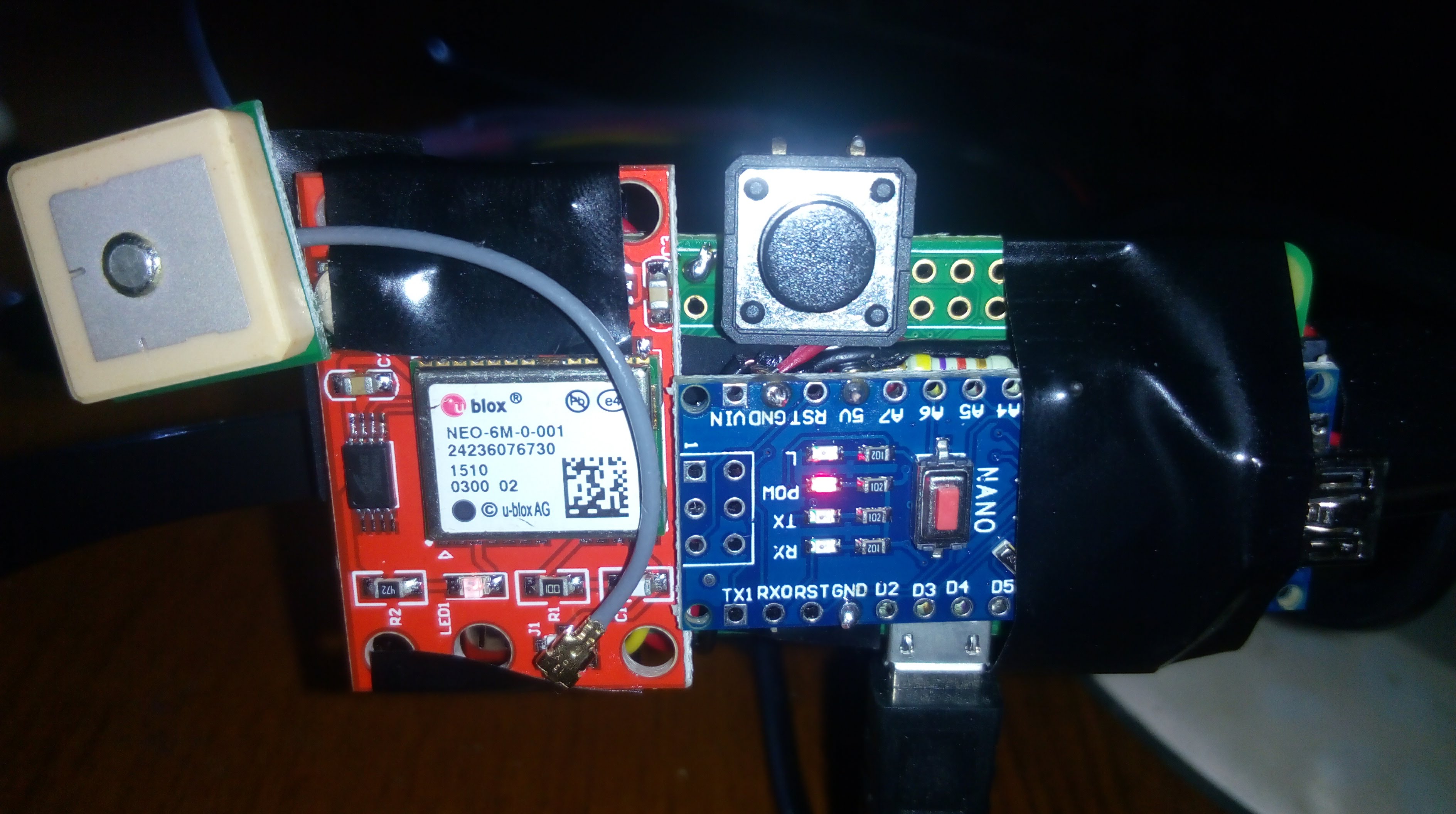
- Secondary controller – Arduino Nano
- Secondary processor – 16 MGh, ATmega328P
- Secondary controller memory – 2 kB SRAM, 1kB EEPROM
- Camera – Sony IMX219
- Camera resolution – 8 Mp (3280 х 2464)
- Supporting video formats – 1080р @ 30fps, 720p @ 60 fps и 640 х 480p @ 90fps
- Matrix size – ¼’
- Pixel size – 1.4μm х 1.4μm
- Blinking sensor – TCRT5000
- Detector type – phototransistor
- Peak operating distance – 2.5 mm
- Emitter wavelength – 950 μm
- Accumulator type – Li-Ion 18650 (Panasonic NCR18650)
- Accumulator size – 3400 mAh (3.7V)
- Weight – 65g (main components), 110g (include glasses, components mount and wires
Main system parameter for “Master” device
- Main controller – Raspberry Pi Zero W
- Main processor – 1 GGh, ARM1176JZ-F
- Graphic processor – VideoCore IV 48+
- Chipset – Broadcom BCM2835
- RAM – 512 Mb DDR2
- Memory – 8 Gb (microSD)
- Communication – WiFi 802.11 b/g/n, Bluetooth 4.1
- Connectors – microUSB, miniHDMI
- Screen size – 2.8’
- Screen resolution – 320x240px
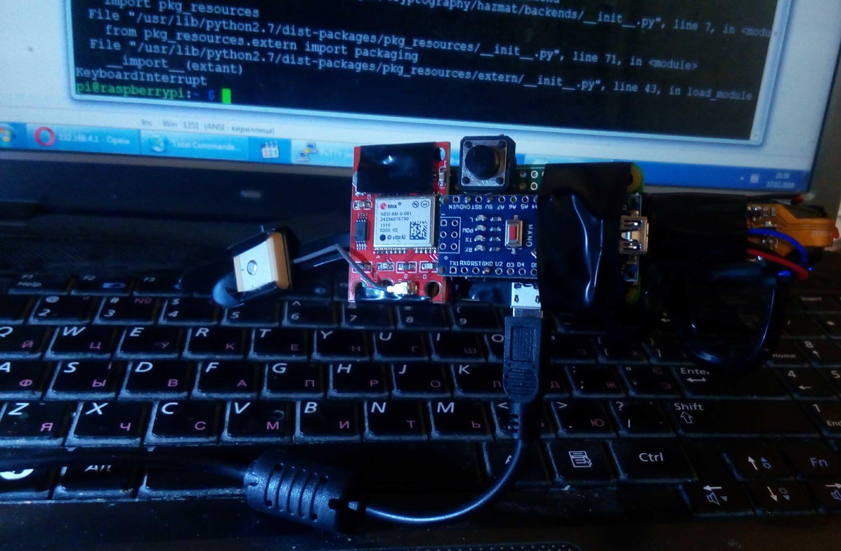
Components
- Raspberry Pi Zero W
- Paspberry Pi Camera
- SD-card (min 8 Gb)
- Arduino Nano
- IR-sensor TCRT5000
- Charge controller TP4056
- GPS module UbloX NEO-6M-0-001
- Li-ion accumulator Panasonic NCR18650
- Glasses (any type)
Further development of the system
-
Adding additional data to send along with the photo (geotag, position of glasses, etc.)
-
Different commands for different flash combinations (double, triple, etc.)
-
Adding a second sensor and using different combinations of two eye blinks
-
Shooting a short video instead of a photo
-
Expanded functionality of the master device (interface displaying connected devices, photo gallery, etc.)
-
Web server to work on the global network
-
Web application to receive data from a web server (displaying your own photos, a gallery of photos of other glasses using various filters, etc.)
-
Mobile application to access data from a web server
-
Formation of business logic for the service
Photos