 Books
Books Technology
 Electronics
 DC motors
 Raspberry Pi Controllers
 All tags
 Programming
 Weaponry
 Projects
Connecting a stepper motor. Controller L298
Article-series: Programming Arduino from scratch #8
Article-series: Arduino, using stepper motors #1
You can use special sensors (encoders) that will tell the controller exactly how many revolutions the motor shaft has made. Then the controller itself will stop the engine after the required number of revolutions, regardless of the changing load. This way we can be sure that our robot has made the desired movement. This is exactly how classic servos are designed - they use a rotary potentiometer as a sensor (it is this that limits the angle of rotation). However, this method has its drawbacks - we can still only control the power and power-off time. And we can’t control the speed very precisely – we turned off the engine, but it can still rotate for some time by inertia. And for high-speed motors, the shaft may make several extra revolutions during the controller response time.
If we need to provide more precise control of the motor so that it makes an exact number of revolutions or even a fraction of a revolution, then we need to use stepper motors. With their help, you can make very precise movements, because the rotation of the shaft is controlled with an accuracy of several degrees. Thanks to this, such motors can be used for precise movements - in CNC machines, 3D printers and where the capabilities of servo drives are not enough.
Unlike a servo drive, which uses a conventional DC motor, albeit with an additional sensor, a stepper motor is initially built according to a different circuit. It has not one winding, but several independent windings. Moreover, the windings are located parallel to the rotor, but at an angle to each other. Applying current to one of the windings causes the rotor to turn a small angle and stop. If you now turn off the current on the first winding and apply it to the next, the rotor will turn another fraction of a revolution. And alternating the voltage supply between the windings will cause the rotor to rotate, and depending on the frequency, this will look either like an abrupt rotation of the motor shaft at a certain angle, or like continuous rotation (in the case of a high frequency of switching windings). Moreover, here we control not only the power but also the exact rotation speed. And we can set the exact angle of rotation of the engine and stop it exactly at a certain angle of rotation.
Unlike a traditional DC motor, a stepper motor typically has four to six wires to connect to. If there are four wires, we have a bipolar engine. Two wires are connected to one winding, two to the other. 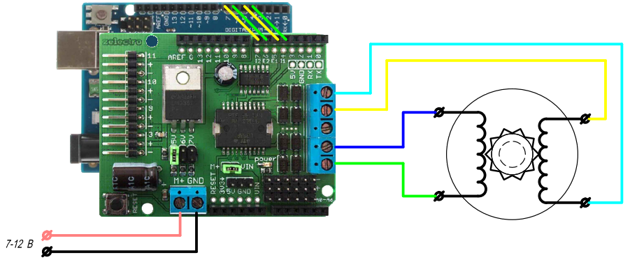
If there are six wires, this is a unipolar motor. Two wires are connected to the ends of each winding and one in the middle. These wires are connected to ground. 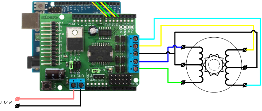
Compared to a bipolar motor, this connection provides higher rotation speed, but reduces torque. If the moment is important to us, then we can simply not connect these wires, i.e. we will turn a unipolar motor into a bipolar one
Thus, connecting both versions of stepper motors to the controller is no different - in both cases we will control two outputs for each winding. We need to choose the right option based solely on the type of engine we have and what is more important to us - rotation speed or torque?
Of course, we can manually write code that will alternate the supply of current to the windings at a certain interval and thus provide control of our motor. But this code has already been written a long time ago and is included in the standard assembly of the Arduino IDE, just connect the Stepper library with the command #include . Now let's create an object of type stepper and indicate which pins our windings are connected to. For this Then we need to indicate one more characteristic of the stepper motor - the number of steps for one revolution of the shaft. The standard motors that are easiest to purchase usually have positioning accuracy of 1.8° or 3.6°. This angle corresponds to the value of one step; accordingly, for one revolution it will be necessary to take 200 and 100 steps, respectively. Let our motor have an accuracy of 200 steps per revolution:
const int StepsForRotation=200; // 200 steps per revolution - 1.8 degrees per step

Stepper stepmotor(StepsForRotation, 4, 7); // the first winding is controlled by output 4, the second by 7
Since when controlling a stepper motor, only the presence or absence of current in the windings is used, we do not need to connect outputs with PWM control. It is enough to use only the I1 and I2 pins. A logical one at the pin will correspond to the supply of rated voltage to one end of the winding and zero to the other. Logical zero - the rated voltage at the second end of the winding and zero at the first. Thus, each of the two windings is controlled by one digital output.
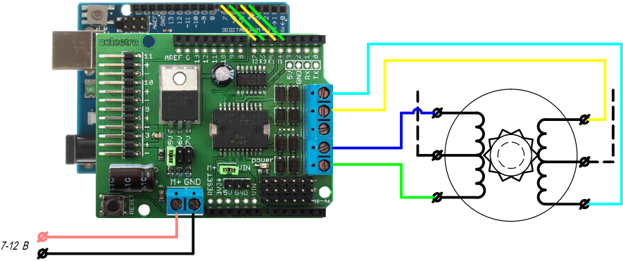
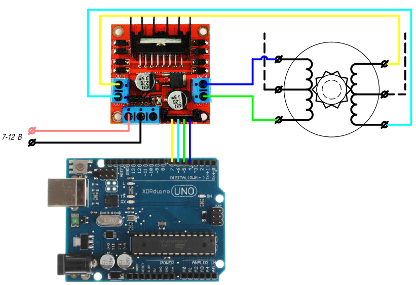
Also, the motor controller can have independent control of each output (that is, when three digital outputs are used to control one pair of outputs - two conventional ones for independent control of each output and one PWM to regulate the value of the supplied voltage). Here we completely independently specify which voltage (high or low) to apply to each end of the winding, i.e. each of the two windings is controlled using two digital pins
const int StepsForRotation=200;
Stepper stepmotor(StepsForRotation, 4, 5, 6, 7);
Connection diagram for this type of motor controller:
In both cases, each winding will receive current for a time sufficient for the shaft to take one step. Then the current from the first winding is removed and supplied to the second (for the next step), or the current is supplied to both windings (to stop the shaft in the current position) or the current from both windings will be removed (for free rotation of the shaft) The frequency of such switchings will be regulated rotational speed. To change the frequency, use the Stepper.setSpeed(int speed);method, which sets a certain rotation speed (in revolutions per minute) for our stepper motor. However, when calling this method, the engine will not start rotating at the specified speed - we are only setting the speed. To move, you must use the Stepper.step(int steps); method, which commands the motor to take steps steps at the speed set by the setSpeed command. Example of use for a motor connected to pins 4 and 7:
/* Control of a stepper motor connected to a controller based on the L298 chip */
#include  // Include the stepper motor control library
const int StepsForRotation=200; // 200 steps per revolution - 1.8 degrees per step
Stepper stepmotor(StepsForRotation, 4, 7); // Initialize the stepper motor 200 steps per revolution, control the windings through digital outputs 4 and 7
void setup()
{
stepmotor.setSpeed(60); // Set the rotation speed to 60 rpm (1 rpm)
}

void loop()
{
stepmotor.step(100); // We send a command to the motor to take 100 steps (half a revolution)
delay(1000); // Wait one second
stepmotor.step(-100); // We send a command to the motor to make 100 steps (half a revolution) in the opposite direction
delay(-1000);
}
After loading onto the controller, the motor connected to it will make half a revolution at a speed of 60 rpm (1 rpm, i.e. it will take 0.5 seconds for half a revolution), stop for one second, then turn at the same speed for half a turn in the opposite direction.
It must be remembered that here we cannot directly influence the speed of rotation - only the frequency of steps. And if for medium and high rotation speeds this is not so important, then at low speeds the intermittent rotation of the shaft will be clearly noticeable. For example, if the speed is set to 1 revolution per minute, the motor shaft will not rotate slowly at 6 degrees per second. It will turn 1.8 degrees as quickly as possible, then stop for a third of a second ms, then turn another 1.8 degrees, etc. For medium speeds, such an intermittent value will not be so noticeable, but frequent clicks (with the frequency of switching of the windings) are clearly audible. Therefore, in cases where slow and smooth movement is needed, using stepper motors directly will not work - you will need to add a reduction gear or use traditional DC motors.