 Books
Books Technology
 Electronics
 DC motors
 Raspberry Pi Controllers
 All tags
 Programming
 Weaponry
 Projects
Connect a DC motor. Microcircuit L298P
Article-series: Programming Arduino from scratch #7
Article-series: Arduino, using DC motors #1
In principle, ordinary electric motors can be easily used without controllers - just connect the winding to a DC network, and the motor will work. Those. You can connect a regular relay to the motor power circuit and control it from the controller. But we are not happy with this option, because we don’t just want to turn the engine on/off, but also regulate the speed and direction of rotation.
Let’s immediately decide that you cannot connect the motor to the controller directly. The current supplied by the controller is insufficient for movement. In addition, the engine can operate in generator mode and burn the controller. Therefore, special amplifiers are used for connection, most often already assembled into a microcircuit. For not very powerful engines, which we will most likely use, these microcircuits are quite sufficient.
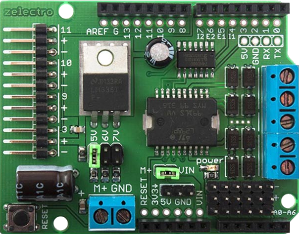
One of the most common motor driver options is L293 or L298 (they differ in the presence or absence of built-in protective diodes). For our purposes, the L298 is quite sufficient, especially since we will not be using a bare microcircuit, but one already soldered onto a board with all the necessary components. There are many versions of this board available, the most convenient one can be considered the “motor shield” version for the Arduino UNO board:
Connecting such a shield does not require soldering at all; just place it on top of our controller.
To control one motor, you need at least two wireless outputs (one to set the direction, the second - the speed). Moreover, the one responsible for the speed must support PWM (marked on the controller as PWM ~) As you can see on the motor shield itself, pins 4, 5, are marked as used 6, 7 (depending on the motor shield model, the numbers of outputs used by it may differ)
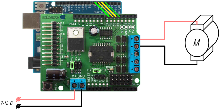
Now let's get down to catering. Motor-shield is capable of being powered by the controller or powered independently. To switch, use a special jumper on the shield. If it is closed, then the controller and motor-shield power circuits are closed. Those. we can supply power either to the “Vin” and “Gnd” outputs of the controller, or to the power terminal block on the shield. This option can be used under the following conditions:
The motor-shielda supply voltage is within the recommended range of 7-12 V for powering the controller
The power of the connected motors corresponds to the power supply. If the supply current is insufficient, a voltage drop in the power circuit will occur. And since it is shared with the controller, this can lead to incorrect operation and even a reboot.
If you remove the jumper, the power circuits of the controller and shield will be independent. That is, you will need to connect power for the motors to the motor-shielda power terminal block. And the controller should be powered from another source (either with a voltage of 7-12 V via “Vin”, or 5 V via the “5V” pin). In this case, we can use more powerful motors ( up to 18V - the maximum voltage for Motor shielda, more powerful ones allow even 36 V). At the same time, we will not be afraid for the controller, the operation of which will not depend on the power part of the drive. But for this we will have to pay for some complication of the power circuits. In addition, But for a mobile robot, it doesn’t always make sense to have two independent power circuits; it’s much easier to power everything from one battery)
The choice of power option is up to the user. But since we will be connecting not very powerful motors, we will be satisfied with the option with a common power supply
The DC motor has only two outputs, we connect them to the terminal block on the motor-shield (two upper or two lower terminals, the central one is connected to ground)
Now let's proceed directly to engine control. To start the engine, it is enough to apply a voltage of 5V to output “E1” (according to the diagram, connected to digital output 5). Depending on the signal level at output “I1”, the direction of rotation will change.
byte E1=5; // Motor speed control - connection to output 5
byte I1=4; // Control the direction of rotation - connect to output 4
void setup()
{
pinMode(E1, OUTPUT); // Set the operation of the corresponding pins as outputs
pinMode(I1, OUTPUT);

digitalWrite(E1, HIGH); // The ENABLE pin is high and the motor is running at maximum speed

digitalWrite(I1, HIGH); // Pin I1 is set to a high logic level, the motor rotates in one direction
}
void loop()
{

}
To change the direction of rotation, we change the signal at output I1. To stop the engine, apply low voltage to output E1
byte E1=5; // Motor speed control– connection to output 5
byte I1=4; // Control the direction of rotation - connect to output 4
void setup()
{
pinMode(E1, OUTPUT); // Set the operation of the corresponding pins as outputs
pinMode(I1, OUTPUT);

}
void loop()
{
digitalWrite(E1, HIGH); // The ENABLE pin is high and the motor is running at maximum speed

digitalWrite(I1, HIGH); // Pin I1 is set to a high logic level, the motor rotates in one direction
delay(2000); // Wait 2 seconds
digitalWrite(I1, LOW); // Pin I1 is set to a low logic level, the motor rotates in the opposite direction
delay(2000); // Wait another 2 seconds
digitalWrite(E1, LOW); // Pin E1 is set to a low logic level, the motor stops
delay(2000); // Wait another 2 seconds
}
The result is rotation of the engine in one direction for 2 seconds, change direction for another two seconds and stop for the same time. Then the cycle repeats.
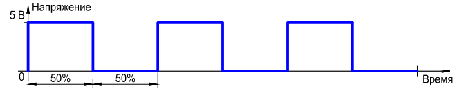
Now let's try to adjust the speed. The Arduino controller cannot supply arbitrary voltage to the digital outputs (they are digital because they only have two states - HIGH (5 Volts) and LOW (0 Volts)). But it can switch these states very quickly (500 times per second, or more precisely, with a frequency of about 490 Hz).
50% of the time the signal is high - corresponds to a final average voltage of 2.5 V
25% of the time a high signal is supplied - corresponds to a final average voltage of 1.25 V {{img|/src/arduino/PWM-25.png|intexttop|State of the digital output, which is controlled by PWM with a duty cycle of 25%} }
10% of the time a high signal is supplied - corresponds to a final average voltage of 0.5 V 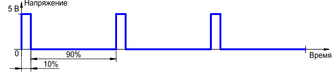
A high signal is supplied from 10% to 50% of the time - corresponds to a smooth increase in voltage from 0.5 to 2.5 volts 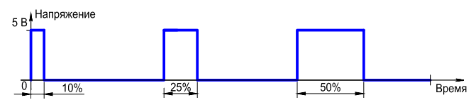
The graphs shown give only a general idea, in reality the switching frequency is so high that we simply will not be able to see the flickering of the LED or jerking of the PWM controlled motor
In order to drive a pin using PWM, it must first support it (for UNO, all pins that support PWM are marked "~"). To output the desired value, use the command analogWrite(value)We can issue a command to press out one of 255 levels (i.e. 1 level - 0.019 volts) That is, the command analogWrite(5, 255) will push 5 volts onto the fifth pin (the same as digitalWrite(5, HIGH)), analogWrite(5, 128) - gives us 2.5 volts, analogWrite(5, 25) - 0.5 volts.
Now let's use PWM to control the motor:
byte E1=5; // Motor speed control - connection to output 5
byte I1=4; // Control the direction of rotation - connect to output 4
void setup()
{
pinMode(E1, OUTPUT); // Set the operation of the corresponding pins as outputs
pinMode(I1, OUTPUT);

}
void loop()
{
analogWrite(E1, 255); // The ENABLE pin is 5 volts, the motor is spinning at maximum speed
digitalWrite(I1, HIGH); // Pin I1 is set to a high logic level, the motor rotates in one direction
delay(2000); // Wait 2 seconds
analogWrite(E1, 128); // The ENABLE pin is 2.5 volts, the motor is spinning at half maximum speed
delay(2000); // Wait another 2 seconds
analogWrite(E1, 25); // The ENABLE pin is 0.5 volts, the motor is spinning at one tenth of maximum speed
delay(2000); // Wait another 2 seconds
}
Now the engine changes its speed at certain points in time. Note that if you try to set the RPM to a very low speed, the engine may hum but not move. This is due to the fact that the supplied voltage is simply not enough to overcome the frictional forces and inertia of the rotor. Therefore, we cannot control the engine at low (about 10-20% of the maximum) speeds.