 Books
Books Technology
 Electronics
 Programming
 Web-interface
 Graphical interface
 Windowed Application
 Video
Video Images
 Audio
Audio Text
Text HTML
HTML Lof-files
 Neural networks
 All tags
 Weaponry
 Arduino
 Projects
Pulse generation system with configuration specified by the Gantt chart
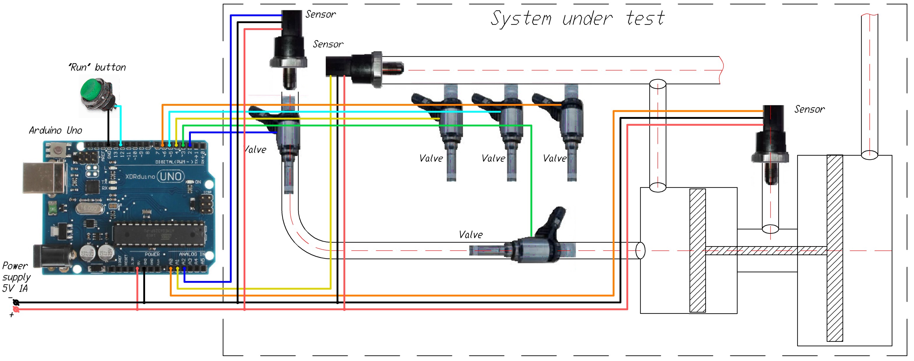
Designed for testing mechanical systems (for example, the fuel system of a car) on a bench using emulation of signals that are normally generated by the on-board computer in operating mode. The serial on-board computer does not always allow you to vary the parameters in the required range. Therefore, this system is used, to which the sensor outputs and control of actuators (molds, valves, etc.) are connected.
Since the controller generates logic signals with a voltage of 5V, sub-sensors and actuators need to be connected through additional circuits to lower or increase the voltage or through high-speed relays.
The pulse sequence is set programmatically by changing the firmware of the controller connected to the PC.
The start of pulse generation can be tied either to the end of the previous sequence or to the activation of a connected sensor (the appearance of a logical zero or one) or to the pressing of control buttons.
Pulse programming
The sequence of pulses is set programmatically by creating objects of the Impulse type in the appropriate place in the firmware
The following structure is used for this:
Impulse(ValvePin, Start, Time, Pause, Number, TriggerPulse, TriggerSensor, TriggerLimit)
Here:
ValvePin – number of the controller pin to which the pulse will be generated;
Start – pulse turn-on delay after start, ms;
Time – Pulse duration, ms;
Pause – Delay between pulses, ms (optional parameter, by default Pause=0);
Number – Number of pulses (optional parameter, by default Number=1);
TriggerPulse – The number of the previous sequence, the completion of which will trigger the start of the current sequence. (optional parameter, by default TriggerPulse =-1);
TriggerSensor – Number of sensor which trigger start of pulse sequence (optional parameter, by default TriggerSensor=-1);
TriggerLimit – value from the sensor, the excess of which will trigger the start of the current sequence. Indicated in the range from 0 to 1024, which corresponds to the voltage on the corresponding pin from 0 to 5V in steps of 0.005V (Optional parameter, by default TriggerLimit=615, which corresponds to triggering at a voltage above 3V);
[!NOTE]
If the last three optional parameters are not specified, then the pulse delay will be counted from the beginning of the operating mode (pressing the “Start” button)
Examples of a task for different pulses configurations:
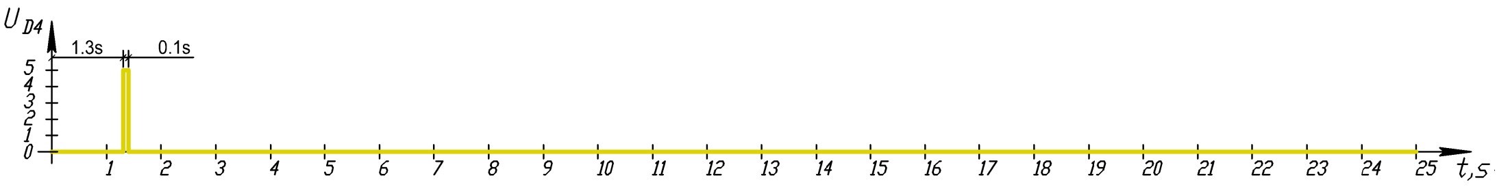
Formation of a single impulse:
For example Impulse(2,1300,100) command will generate one 6ms long pulse on pin #4 1.3 seconds after the "Run" command.
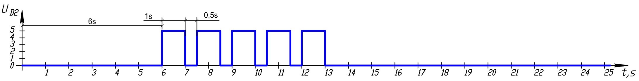
Formation of repeating pulses sequence:
For example Impulse(2,10000,1000,500,10) command will generate a sequence of 10 pulses on pin #2, the duration of each pulse is 1 second, the pause between pulses is 0.5 seconds. In this case, the sequence starts 10 seconds after the start command.
A sequence of pulses in which the beginning of one pulse depends on the completion of the previous pulse:
To create a dependency, optional TriggerPulse parameter need to be specified. It indicates the serial number of the sequence, the end of which will serve as the beginning of the current one.
For example Impulse(3,4000,100,300,15,2) command will generate on pin #3 a sequence of 15 pulses 100 ms long with a pause between pulses of 300 ms. Sequence starts 4 seconds after sequence #2 ends
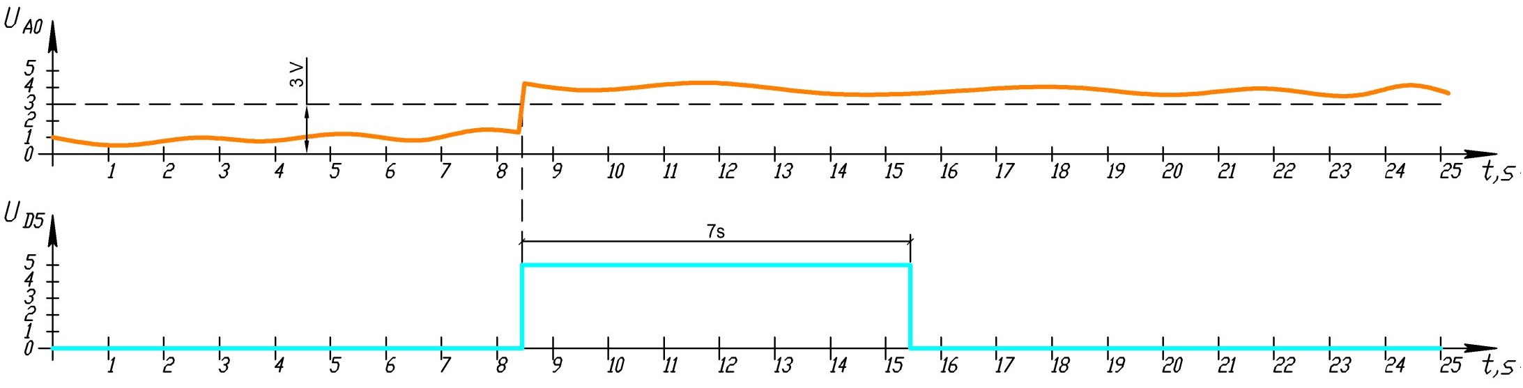
A sequence of pulses that is initiated by sensor readings:
To create a dependency of sequence from the sensor, the optional TriggerSensor parameter need to be specified, It indicates number of sensor which trigger start of pulse sequence By default, the response threshold is set to 3V (threshold for transition from logical zero to logical 1)
For example Impulse(5,0,7000,0,1,-1,0) command will generate one 7-second pulse on pin #3, which will begin at the moment when a voltage greater than 3V arrives from sensor #0.
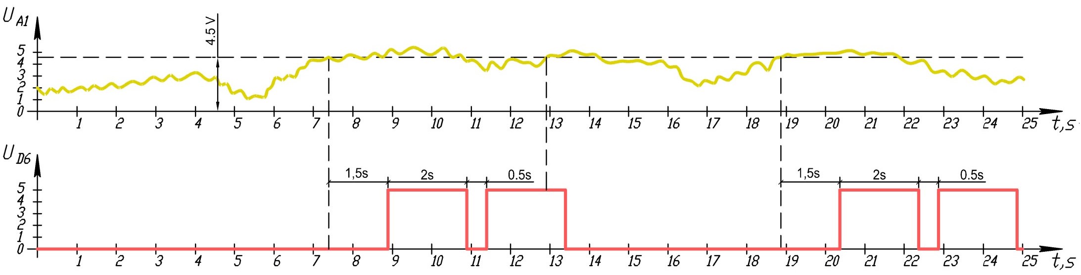
If necessary, trigger can be set to any voltage within the measurement limits; for this, after the TriggerPulse parameter, you must also set the TriggerLimit parameter. The value can be in the range from 0 to 1024, which will correspond to a response voltage from 0 to 5V in steps of 0.005V.
For example Impulse(6, 1500, 2000, 500, 2,1,1, 920) command will create a sequence of 2 pulses with a length of 2000 ms and a pause between pulses of 500 ms. The sequence begins 1.5 s after sensor #1 receives a voltage greater than 4.5 V
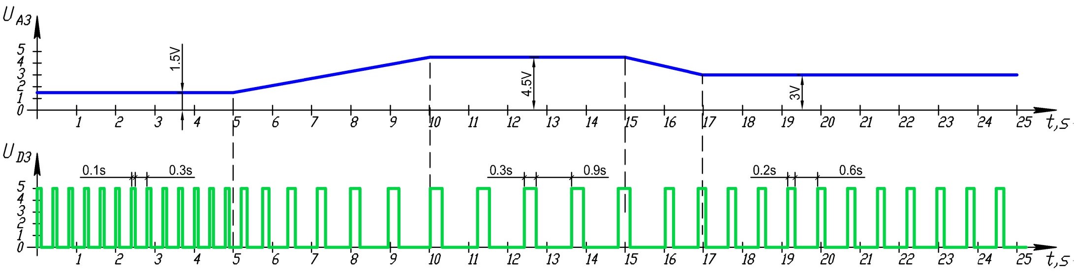
Pulse frequency control depending on sensor readings (frequency control)
Allows to change the frequency of pulses of one of the sequences in proportion to the voltage from the sensor.
To create a dependency, object of type SensorScaler need to be added
The following structure is used for this:
Impulse(SensorNumber, TargetPulseNumber, ZeroPulseDelay, ZeroPulseTime, ZeroPulsePause, StartScaling, TimeScaling,PauseScaling)
Here:
SensorNumber – Number of the sensor that will change the pulse;
TargetPulseNumber – Number of the pulse sequence to be controlled;
StartScaling – The coefficient by which the delay before the start of the pulse sequence will increase;
TimeScaling – The coefficient by which the pulse duration will increase;
PauseScaling – The coefficient by which the pause between pulses will increase;
ZeroPulseDelay – Delay before the start of pulses which corresponds to the readings of the 0V sensor (optional, by default ZeroPulseDelay =-1);
ZeroPulseTime – Pulse duration that corresponds to the 0V sensor readings. (optional, by default ZeroPulseTime =-1);
ZeroPulsePause – Pulse pause that corresponds to the 0V sensor readings. (optional, by default ZeroPulsePause =-1);
[!NOTE]
The values of the scaling factors
StartScaling,TimeScaling,PauseScalingcorrespond to how many times the initial value will change when the voltage from the sensor is 5V. For example, a factor of 2 will double the initial value of the parameter at a voltage of 5V, and increase it by only 20% at a voltage of 0.5V. A negative coefficient will decrease the parameter relative to the original value. For example, forTimeScaling=-1at a voltage of 2.5V the parameter value will be 50% of the original, at a voltage of 0.5V – 10% of the original
[!NOTE] A value of 0 for
StartScaling,TimeScalingorPauseScalingscaling factors will not change the corresponding parameter depending on the sensor
[!NOTE] A value of -1 for the
ZeroPulseDelay,ZeroPulseTimeorZeroPulsePauseparameters will not additionally set the parameter value to 0, i.e. only the original value of the parameter will be taken into account.
For example, following combination of commands:
Impulse(3, 0, 100, 300, 100)
SensorScaler(3, 3, 0, 3.33, 3.33, 1, 0, 0)
will generate a series of pulses on pin D3, the parameters of which will correspond to the voltage on pin A3. For a voltage of 1.5 V – pulse length is 100 ms with a pause of 300 ms, for a voltage of 4.5 V – 300 ms and 900 ms, respectively
Main characterisitics
- Main controller – Arduino Uno
- Processor – 16 MGh, ATmega328P
- Controller memory – 32 KB Flash + 2 kB SRAM + 1kB EEPROM
- Controller analog input – 10 bit (1024 levels)
- Controller analog input resolution – 0.00448V
- Output voltage for pulses – 5V
- Max pulse frequency – 1000Hz (1ms duration)
- Nominal input power –5 B 0.5A
- Operating temperature: – -10..+85 °C)
- Dimensions – 50x25x20mm (components assembled in case)
- Weight – 50 g (with plastic case)
Components
- Arduino Uno – 1pcs.
- Momentary Push Button – 1 pcs
- Valves – up to 12pcs
- Analog sensors – up to 6pcs
Wiring diagram
Further development of the system
- Adding additional options for the logic of pulse formation and triggers (appearance of a signal of a certain frequency, etc.);
- Adding a graphical interface for generating a pulse task (desktop or mobile application);
- Adding control elements for running independent testing programs, parameters sets etc.
- Wireless control (Bluetooth, 1.2 GHh etc.);
- Adding an LCD screen displaying the status of pulses and sensor readings in real time;
- Logging of all data;
- Adding a trigger for exceeding the reading with additional actions (turning on/off the relay, issuing logical signals, sound alarm etc.);
- Adding an independent power supply;
- Web interface;
- Transfer and save data to the cloud;