Books
Books Technology
 Electronics
 Programming
 Web-interface
 Graphical interface
 Windowed Application
 Video
Video Images
 Audio
Audio Text
Text HTML
HTML Lof-files
 Neural networks
 All tags
 Weaponry
 Arduino
 Projects
Ultraviolet 3D Printer with table swinging
3D printer for print from UV curing resin with table swinging for better mixing and manual control of table lifting
The part is printed from a liquid resin that hardens under the influence of ultraviolet light.
To do this, a flat table is immersed in the liquid resin to the depth of one printing layer. After this, the ultraviolet projector projects a black and white image of the desired layer onto the table. In the place where the light fell (corresponding to the white area in the monochrome image of the layer), the resin hardens. At the end of the exposure time, the projector turns off (switches to displaying a black frame) After this, the table is immersed in the resin deeper to the thickness of the next layer and the frame with the next layer of the part is turned on. CreationWorkshop software is responsible for generating images of layers, delivering images to the projector and controlling the movement of the table during the printing process.
[!WARNING] To avoid eye damage, the printing area must be covered or protected by tinted glass that is opaque to ultraviolet light!
Due to the fact that the thickness of the layers is quite small, after immersion the resin does not always reach the entire surface of the part. Because of this, pores or internal cavities may appear, which impairs the strength of the finished product. In order to avoid this, use the table Swing function during breaks between exposures; the table rocks several times, which allows the resin to be more evenly distributed over the entire surface of the printed part.
Printer mechanics
The main printing table is immersed in a container with a liquid resign and mounted on ball screw gears connected to stepper motors. This allows the table to be raised and lowered with high precision.
Limit switches are installed in the upper and lower positions of the table, which signal the controller to block further movement.
An ultraviolet projector with appropriate optics is installed above the table, connected to the control PC via an HDMI cable.
The main controller is connected to the same PC via USB (with an emulated COM port) through which G-commands are transmitted to control the printer.
The resin tank can be tilted at a small angle using a stepper motor. Limit switches are also installed in extreme positions to stop swinging To control the printer, a positions latching joystick is used, which allows you to raise and lower the table manually.
In print mode, any movement of the joystick stops the current movement. In normal mode, pressing and releasing the joystick down begins moving down until the lower limit switch is activated. If during this movement you press and release the joystick up, the movement will stop. If you press and release the joystick up again, continuous upward movement will begin until the upper limit switch is activated or the joystick moves and releases down.
Controls in the Creation Workshop program can also be used to control the table.
Creation Workshop Settings
In the Creation Workshop application, load the profile for working with the printer (Configure->Configure Slicing Profile->Machine Profile->mUVe.1.3) Set the layer thickness (Configure->Configure Slicing Profile->Settings->Slice Tickness (mm)->0.1)
We set the total cycle time during which all movements of the table and plate will be made for one layer (Configure->Configure Slicing Profile->Lift and Sequence->Lift and Sequence time (ms)->8000) This time should not be less than, than the full cycle of movement of the work plate and the swinging table, configured in the firmware. Otherwise, the exposure of the next layer will begin before the table and stove return to the working point!
When changing settings and before printing, each time open the 3D model and use the Slice command with the mUVe.1.3
Printing sequence
At the start of printing, it is assumed that the printer is set to the zero position. You can optionally reset the controller.
At startup, exposure of the first frame begins for 1 second (change Configure->Configure Slicing Profile->ettings->Explosure time (ms)->1000). The projector then starts showing a black frame. When the lens servo shutter is used, it closes.
Immediately after the end of the exposure, the swinging table begins to move downward at a speed of 10 mm/sec (variable TiltDownSpeed=3200) The table stops after 2 seconds having passed 20 mm (variable StepsToRaiseLowerVat=6400)
After 1.2 seconds from the end of the exposure (variable TimeForRaiseBuild=1200)
lifting of the working plate begins at a speed of 2 mm/sec (variable LiftUpSpeed = 1600) The plate stops after 2 seconds having passed 4 mm (variable StepsToRaiseLowerBuildPlate = 3200)
After 3.4 seconds from the end of the exposure (variable TimeForGoZeroPos=3400), the lowering of the working plate and raising of the swinging table begins.
The table descends at a speed of 1 mm/sec (variable LiftDownSpeed = 800) and stops after 4 seconds after passing 3.9 mm (4 mm minus the layer thickness).
The rocking table rises at a speed of 5 mm/sec (variable TiltUpSpeed = 1600) and stops after 4 seconds after passing 20 mm
After 8 seconds (variable Creation Workshop->Lift and Sequencetime=8000) the cycle of movements is completed, when using the lens servo shutter it opens. Exposure of the next frame begins.
At the end of printing or when the upper limit switch is triggered, printing ends and the servo valve closes
When changing speeds and distances, you must ensure that all movements are completed before exposure of the next frame begins and set the Lift and Sequence time variable accordingly. After changing it or changing the layer thickness before printing, you must re-use the Slice command with the mUVe profile.1.3
Main system parameters:
- Main controller – Arduino Mega
- Processor – 16 MGh, ATmega2560
- Controller memory – 256kB + 8 kB SRAM+ 4kB EEPROM
- Stepper motors – Nema 17 0.4A
- Stepper motor torque – 26Ncm
- Power supply – 12V 5A
- Ball screw gears step – 4mm
- Minimal printing layer thickness – 0.00125mm
- Exposure time –2..8s (depends on resin, projector power and layer thickness
Printer firmware
Based on modified Marvin firmware for 3D printers.
Print variables and their default settings for the Lift and Sequence cycle time(ms)=8000
int PlatenStepsPerLayer = 80;
Steps to move one layer thickness. Calculated by dividing Slice Thickness (mm) from the Creation Workshop print settings by mm/step For a layer of 0.05 mm, a screw with a pitch of 4 mm and 1/16 microstep = 0.05/0.00125=40 For a layer of 0.1 mm, a screw with a pitch of 4 mm and 1/16 microstep = 0.1/0.00125=80
int StepsToRaiseLowerBuildPlate = 3200;
steps to raise the table between exposures For a screw with a pitch of 4mm and 3200 steps per revolution - 3200 corresponds to a rise of 4mm (~2 sec at 1600step/sec, ~4 sec at 800step/sec)
int StepsToRaiseLowerVat = 6400;
Steps to raise/lower the rocking table For a screw with a pitch of 10 mm and 3200 steps per revolution – 6400 corresponds to a rise of 20 mm (~2 sec at 3200step/sec, ~4 sec at 1600step/sec)
int TimeForRaiseBuild=1200; - Time from the start of the cycle to start raising the work plate
int TimeForGoZeroPos=3400; The time from the beginning of the cycle from which the plate and table begin to return to the working position before the start of the next cycle should not work before the working plate rises to the upper position, and the swinging table falls to the lower
int motorSpeed = 3200; - Movement speed in manual control mode, steps/s
int motorAccel = 12000; - Acceleration of movement in manual control mode, steps/s²
int LiftDownSpeed = 800; - Speed of lowering the working plate, step/s;
int LiftDownAccel = 4000; - Acceleration when lowering the work plate, steps/sec²;
int LiftUpSpeed = 1600; - Speed of raising the working plate, steps/s;
int LiftUpAccel = 12000; - Acceleration when raising the work plate, steps/s²;
int TiltDownSpeed = 3200; - Swinging table lowering speed, steps/sec;
int TiltDownAccel = 12000;- Acceleration when lowering the swinging table, steps/s²;
int TiltUpSpeed = 1600; - Swinging table lowering speed, steps/s;
int TiltUpAccel = 8000; - Acceleration when raising the swinging table, steps/s²;
bool LiftMotorReverse=false; - Inverts the direction of movement for the work plate motor. By default, up is clockwise, down is counterclockwise;
bool TiltMotorReverse=false; - Inverts the direction of motion for the swinging table motor. false – up clockwise, down – counterclockwise. true – down clockwise, up – counterclockwise.
Set of G-codes to control the printer:
Z0– stop the movement of the work table;Z+/-50– continuous movement of the work tableZ+/-10– one revolution of the work table motor (3200 steps)Z+/-1– 1/200 rotation of the work table motor (16 steps)X0– stop the movement of the Swing tableX+/-100– continuous movement of the Swing tableZ+/-10– Movement of the Swing table to extreme positions (upper and lower)Z+/-1– 1/200 rotation of the Swing table motor (16 steps)
Hardware
- Arduino Mega – 1 pcs
- Ramps 1.4 3D printer mainboard – 1 pcs
- Stepper motor– 3pcs
- A4988 stepper motor driver – 2 pcs
- Limit switch – 4pcs
- Power supply 12V 5A – 1pcs
- UV-projector – 1pcs
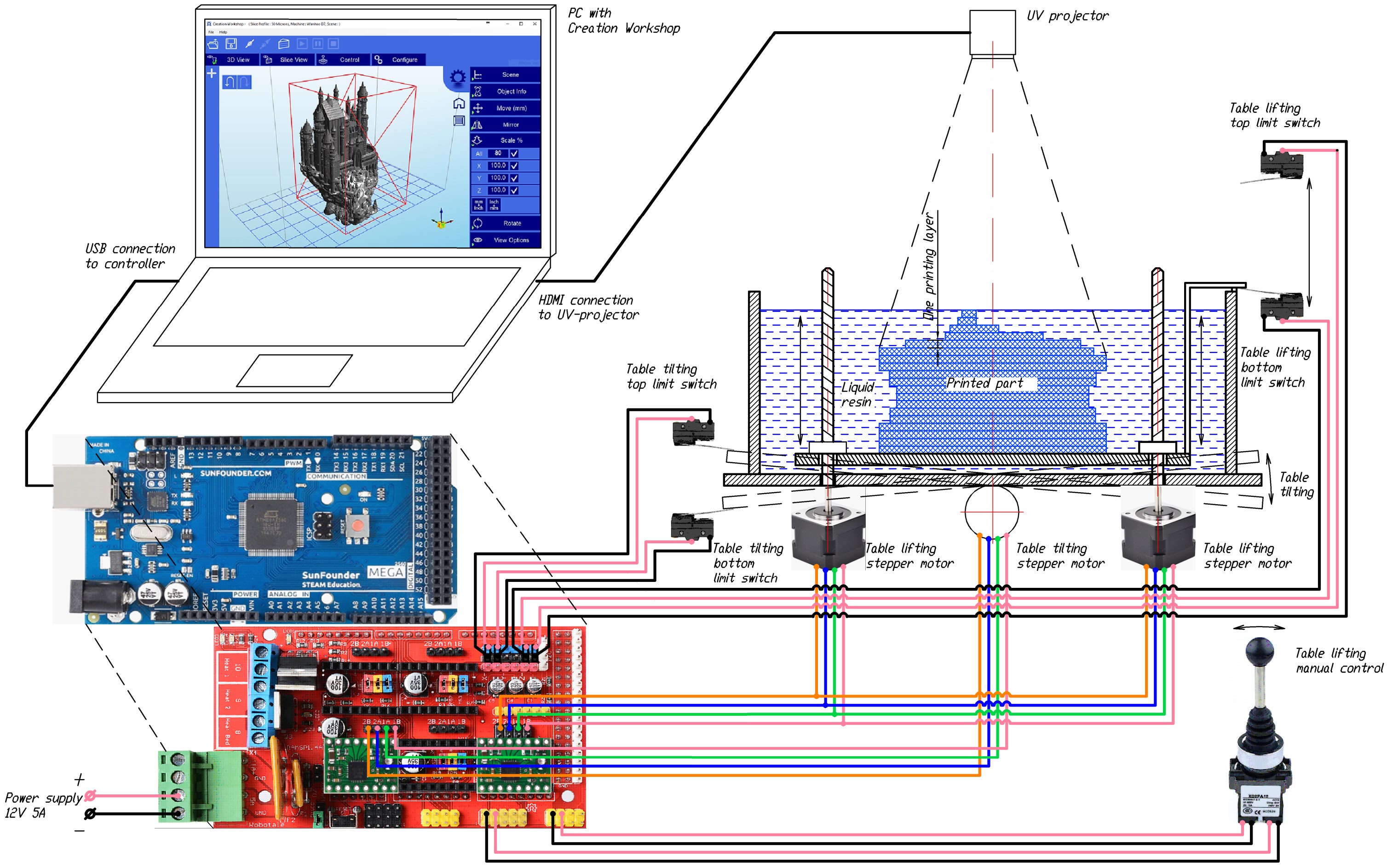
Wiring diagram
Possible further improvements
- Adding additional control elements for printer (stop buttons, analogue parameter controllers etc)
- Adding servo shutter to close projector objective (Reduces stray light).
- Printing without connecting to a PC (based on a set of photographs and control G-codes downloaded to external media)
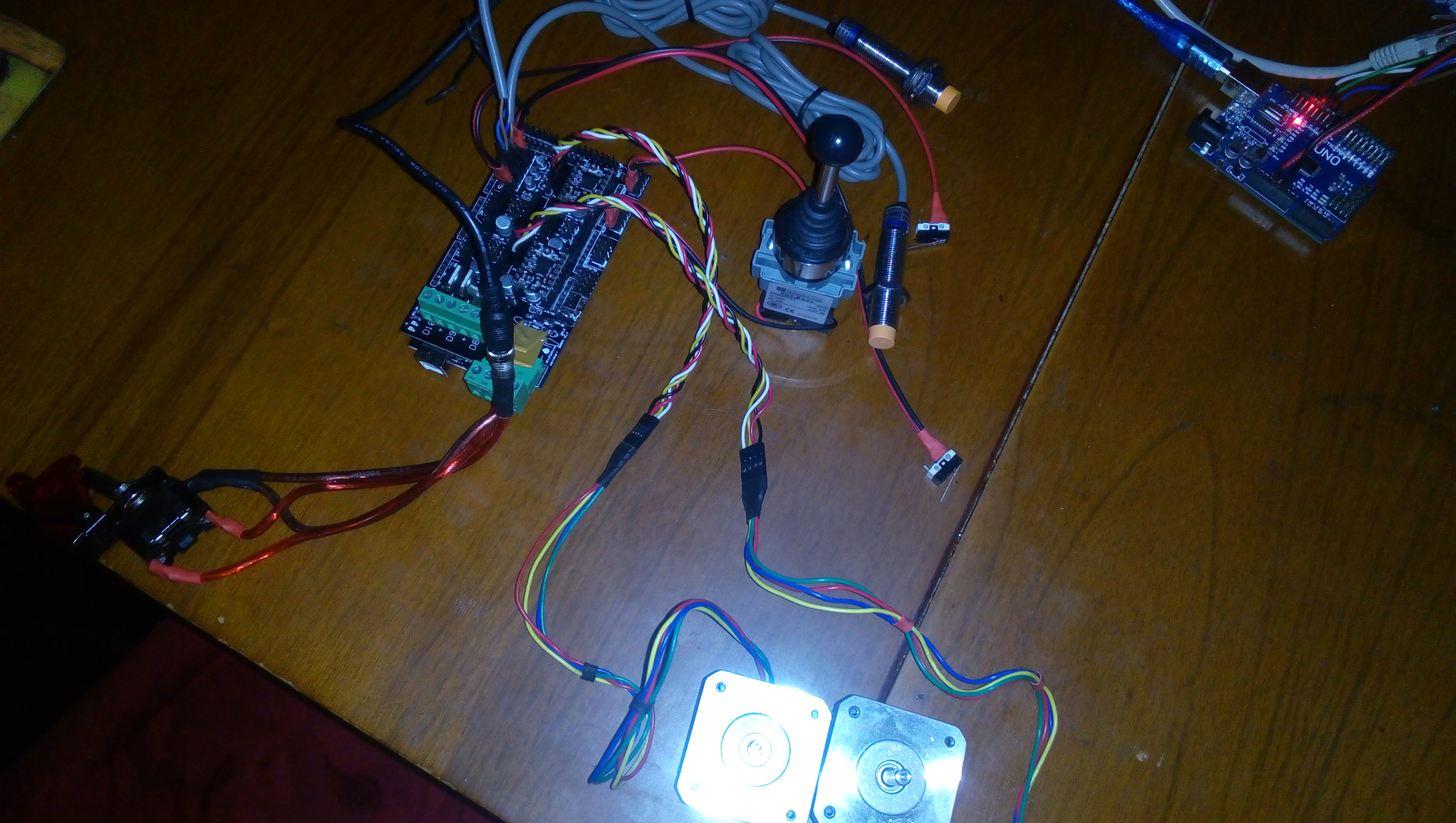
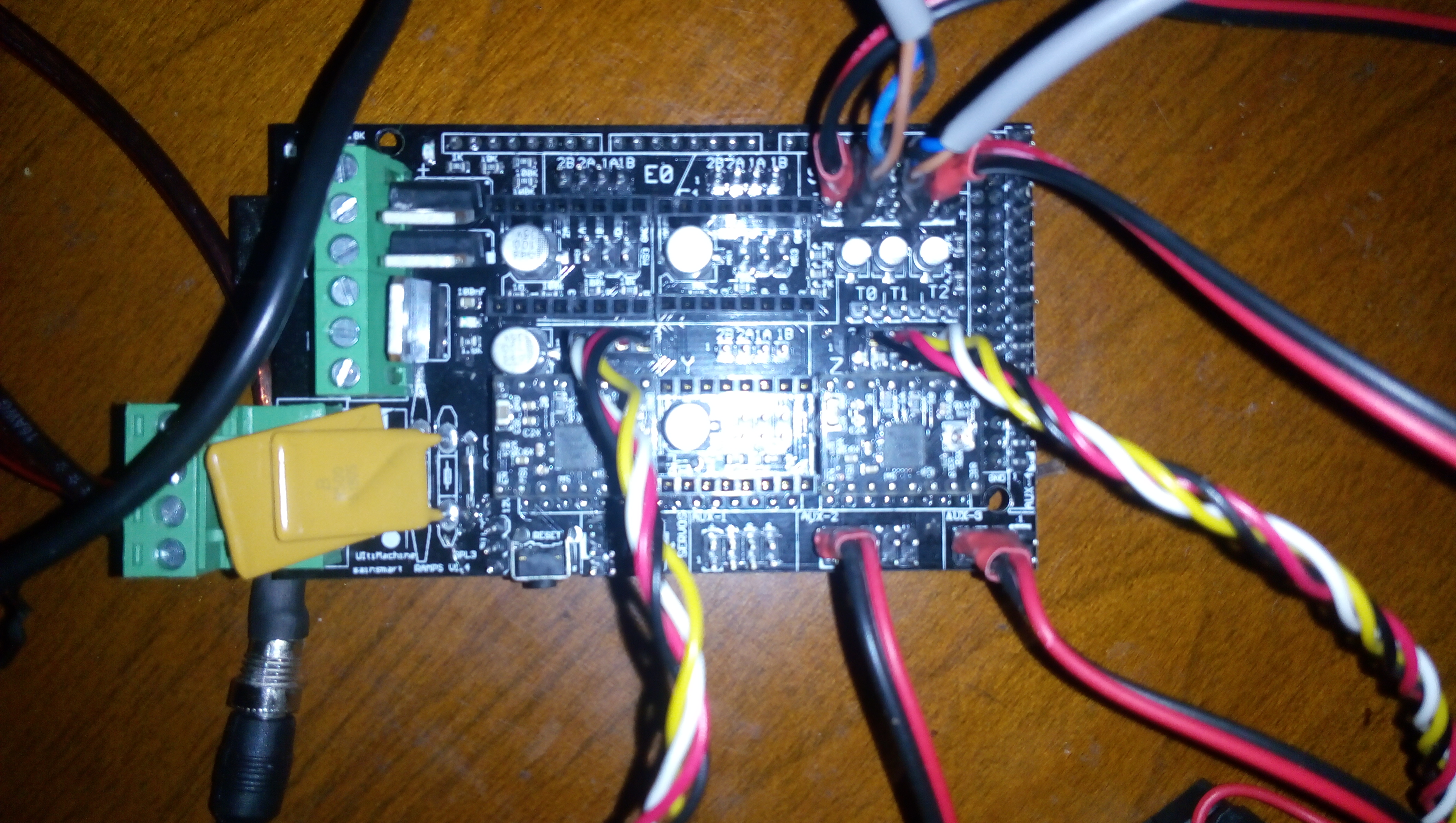
Photos