 Books
Books Technology
 Electronics
 DC motors
 Raspberry Pi Controllers
 Relay
Relay Temperature sensors
 All tags
 Programming
 Web-interface
 Graphical interface
 Windowed Application
 Video
Video Images
 Audio
Audio Text
Text HTML
HTML Lof-files
 Neural networks
 Weaponry
 Projects
Connecting the servo drive to Arduino
Article-series: Programming Arduino from scratch #4
Article-series: Arduino - using_servos #1
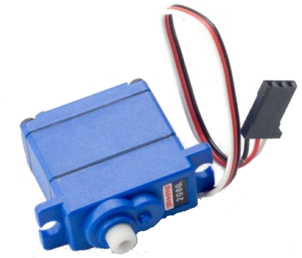 One of the most common parts for creating robots is a servo drive. In fact, it is a small electric motor with a gearbox and a built-in potentiometer. The potentiometer is connected to the output shaft, and along with its rotation, it changes its resistance - accordingly, at any time you can find out about the position of the shaft. Unlike a conventional motor, the built-in electronics drive the motor so that its position corresponds to the setpoint
Typically, servos are not designed for a full rotation; the shaft can rotate at a limited angle (usually 180 degrees). This is quite enough to control the steering wheels or the magipulator. That's why servo drives are most often used for hinges. The main indicator of servo drive power is torque, usually expressed in kg⋅cm. For long manipulators that must lift a decent amount of weight, servos with a torque of 30-40 kg⋅cm or more will be required. If we want to use our servo drive to do not very hard work, then the simplest ones, 1.8 or 3.2 kg⋅cm, are quite enough.
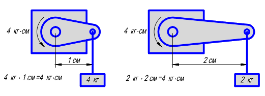 In general, torque is expressed in N⋅m. But for greater ease of calculation, it is often expressed in kg⋅cm (1 kg⋅cm ~ 0.01 kg⋅m ~ 0.098 N⋅m) This is the force that the servo can provide at a certain distance from the axis of rotation. That is, for example, a servo drive with a torque of 4 kg⋅cm can lift a load of 4 kg, 1 cm from the axis, or 400 grams, but already at a distance of 10 cm from the axis. If we want to make a manipulator, then we need to estimate the weight of the moving parts and select the appropriate servos for each joint.
 The servo drive is connected using three wires - a standard pair of power and ground and one control. For low power servos, all three can be connected to the controller directly. But if we use many servos or several, but powerful ones, then the capabilities of the controller will no longer be enough. It is necessary to connect only the control output to the controller, and supply power to the rest independently.
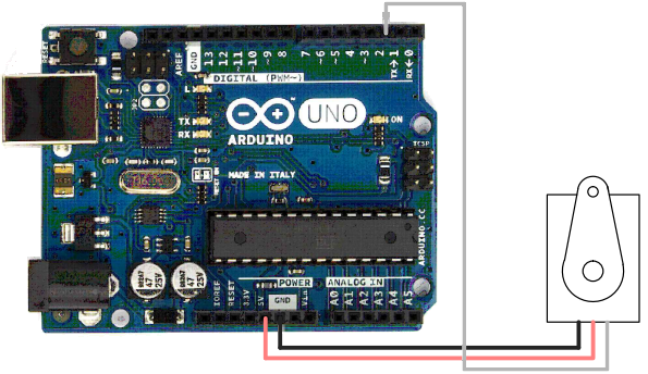
For more convenient connection of a large number of servos, there are special expansion boards on which the contacts for each servo are already assembled in groups of three, which greatly simplifies the connection. But this is for complex projects, such as spider-like robots, where each leg joint is controlled separately. We will consider the simplest option with one servo drive connected directly to the controller.
We power the servo drive from the “5V” pin (red wire), connect the ground to the “Gnd” pin (black wire). The control (white wire) can be connected to any of the free outputs, for example, to pin number 2 (controller outputs 0 and 1 are used for communication via the serial interface, so using them is not recommended)
To control the servo drive, the standard Servo class is used. We need a procedure attach(), which is used to initialize the servo and write() to control its movement:
#include  // Include the library for working with the servo drive
Servo servo1; // Create one object of type “servo drive”
void setup()
{
servo1.attach(2); // Explain to the controller that the servo drive control wire is connected to pin 2
servo1.write(90); // Command the servo to take a 90 degree position, which corresponds to the middle position
}
void loop()
{
}
When we run our program, the connected servo will take a position of 90 degrees. If he is already in it, then nothing will happen. Let's try to smoothly change the position from minimum to maximum:
Servo servo1; // Create one object of type “servo drive”
void setup()
int angle = 0; // Variable that stores the servo position
{
servo1.attach(2); // Explain to the controller that the servo drive control wire is connected to pin 2
}
void loop()
{
For (angle = 0; angle <= 180; angle += 1) // Start moving from 0 to 180 degrees
{
servo1.write(pos); // Command the servo to accept the new position
delay(10); // Pause before next move
}
}
A delay of 10 ms gives a rotation of 1 degree in 10 ms, i.e. in 1 second we will rotate by 1000/10 = 100 degrees, and the entire cycle will take 1.8 seconds.
In addition, we need to have a separate variable in which the current position of the servo will be stored. The fact is that the controller cannot know what position the servo is currently in. Although there is a potentiometer that measures the current rotation angle, this data is only used by the internal electronics of the servo itself. We can only give the command to take the necessary position. Therefore, we need to separately record each change in position in the corresponding variable, which we will use if we need to calculate something based on the current position of the servo