 Books
Books Technology
 Electronics
 DC motors
 Raspberry Pi Controllers
 Relay
Relay Temperature sensors
 Analog sensors
 Digital sensors
 ADC
ADC Bluetooth
 Radio communication 2.4 GHz
 LCD-screen
 All tags
 Programming
 Web-interface
 Graphical interface
 Windowed Application
 Video
Video Images
 Audio
Audio Text
Text HTML
HTML Lof-files
 Neural networks
 Weaponry
 Projects
Water pumping control system
The system for installation on a pipeline for liquids pumping and control of the transportation process
Includes fluid flow sensors, motor current sensor and control relay for online control of process parameters, logging, emergency automatic and manual control of pumping.
To process data from sensors and control the system, a separate program is used (it works on any computers with Windows OS (XP, 7, 8.10 versions)
Controller and the workplace are separated from the location of the engine and sensors at a distance of 10-20m (a standard 8-wire network cable is used to transfer all data)
Functions
- Automatically turn on / off the engine
- according to a given program,
- depending on the readings of sensors
- by command from a PC.
- Data can be transferred to PC via USB cable.
- Processing data from sensors and control pump engine via desktop application (Microsoft Windows compatible)
- Logging of process (with saving of logs and opening previously opened data)
Main system parameters:
- Nominal water consumption – 200 l/min (two flows 100 l/min each)
- Maximal water consumption – 240 l/min
- Working temperature – 0..80 °C
- Working moisture – 35%..90% RH
- Liquid temperature – 0..120 °C
- Nominal pressure – 20 bar
- Peak current on the motor windings – 50 А (each winding)
- Pump motor voltage – up to 230V
- Pump motor current – up to 30A
Flow control application
Desktop application for work of engraving machine. Developed on C++ using .Net framework.
Can work on any PC with operating system supporting .NET framework (windows 7,10,11)
Flow control system cotrol application. Version 1.01
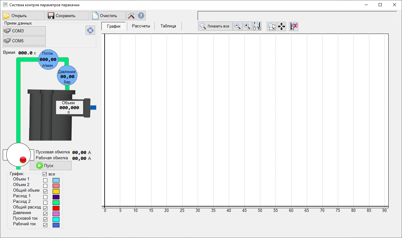
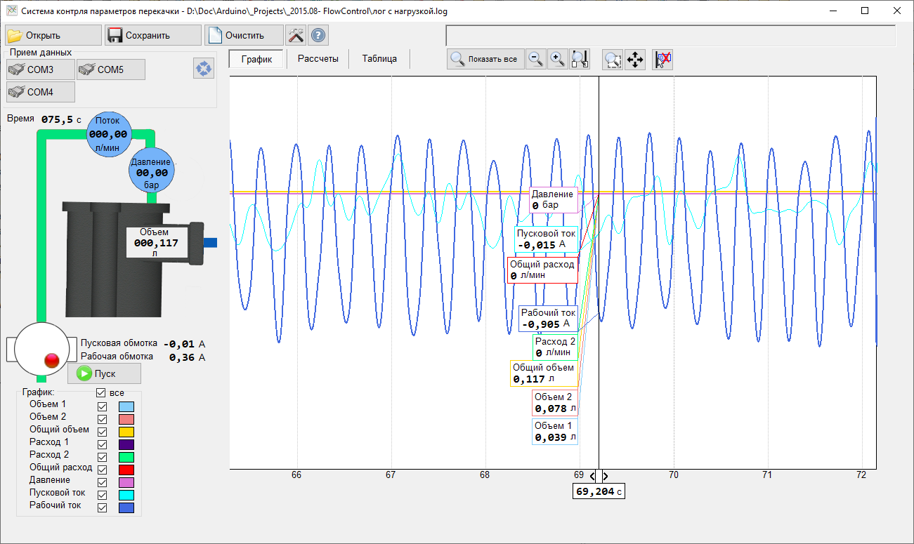
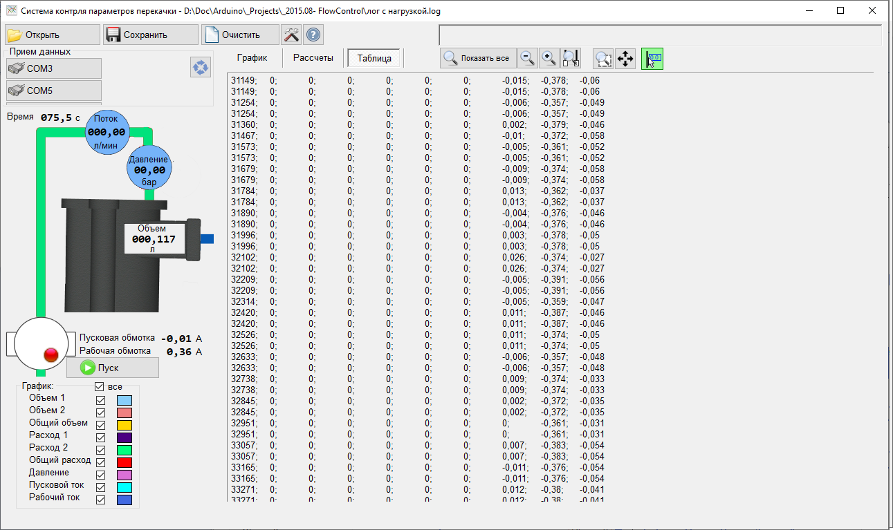
The main window contains a mnemonic diagram with sensor values and control buttons. In the central panel, all values can be displayed in graphical or tabular form.
The buttons in the top row are used to zoom (you can also use the scroll wheel), reset the zoom (double click the middle mouse button), move the field of view on the chart (you can use the middle mouse button), show the slider with the current values.
An independent setting of the line display style for each parameter can be applied using the panel on the left side of the window.
The main menu includes buttons to save and open previously saved logs, system parameters, and a console with current commands sent to the controller and received responses.
A separate panel is designed to select the port to which the controller will be connected.
Main functions of flow control application:
Real-time acquisition of the following data:
- Consumption of liquid flowing through the pipeline (by independent pipelines and total)
- Amount of liquid pumped over a certain period of time
- Pump motor current (for working and starting winding)
- Liquid pressure value
Engine control - manual or automatic on/off
Keeping a log of all received data
- Logging frequency up to 20 polls / sec in text form
- Log output in text format
- Log output in the form of a graph with the ability to scale, disable the display of unnecessary data, arithmetic calculations.
- Saving a log of sensor readings in text form for subsequent use in calculations (Excel, mathematical packages MatCAD, MatLab)
- Opening previously opened logs with the ability to plot graphs and operations on them
Application settings:
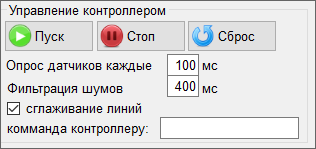
- Manual start, stop and reset of controller
- Change of sensors frequency
- Change noise filtering strength (approximation of several sensor readings in a certain period of time to avoid random peaks and dips in values)
- Smoothing lines on graphs
- Manual sending command to controller and receiving answer
Display parameters for graphical values (independently for each parameter):
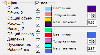
- Enabling the display of each parameter
- Change color and thickness of line
- Change vertical scale to fit in window
Components
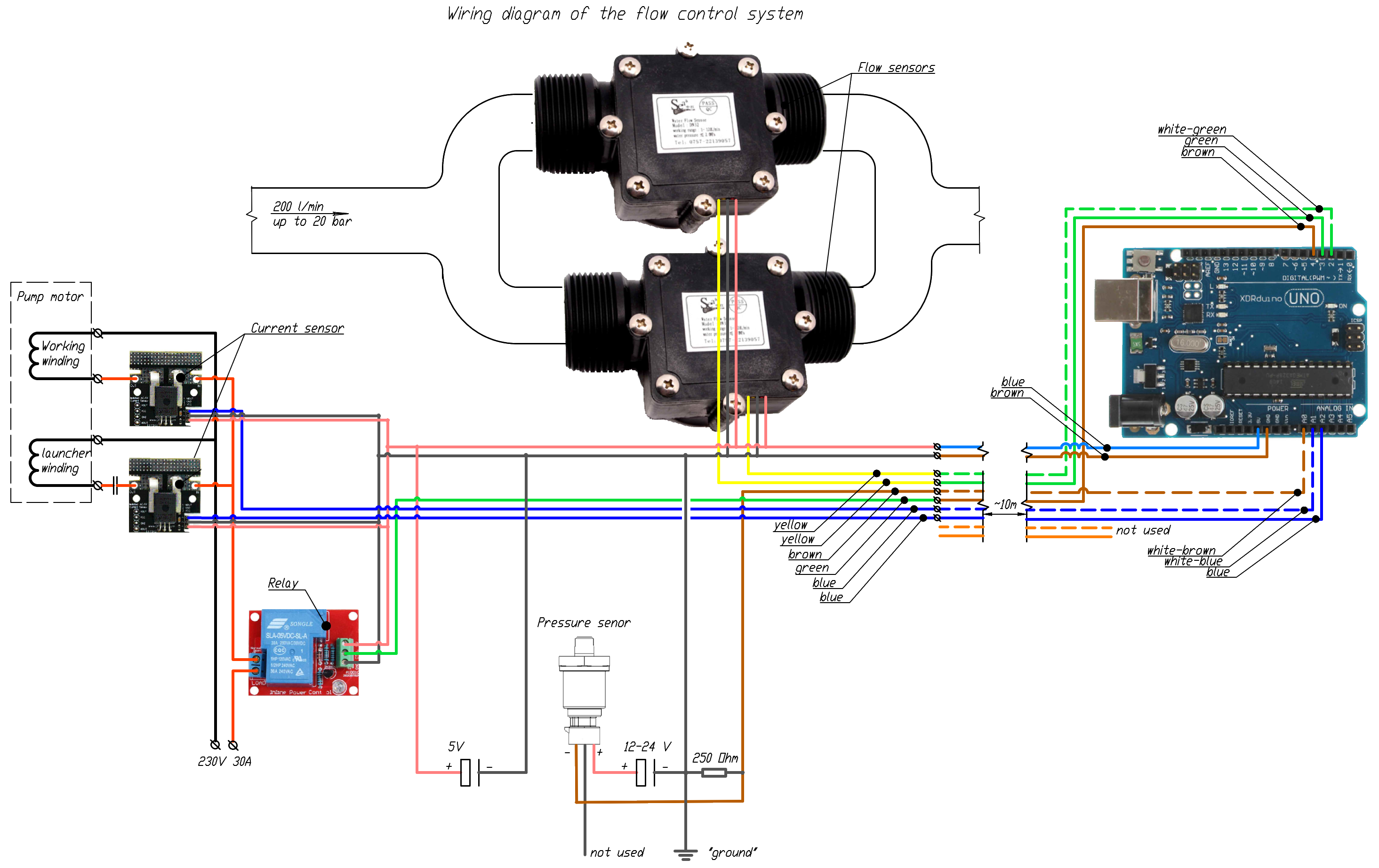
- Controller Arduino UNO
- G1'1/4 water flow sensor (based on Hall sensor) – 2 pcs
- Current sensor ACS758 – 2 pcs
- Pressure sensor MLH025BSB01B
- Relay module (30А 240VAC)
Wiring diagram
Possible further improvements
-
Remote connection (via Bluetooth, IR or radio channel)
-
automatic control according to various patterns, including emergency shutdown upon reaching the critical values of the parameters.
-
Web interface for remote connection
-
SMS informing and control using GSM module.
-
Smooth change of engine operation parameters incl. smooth start.
-
Control program usability improvements