 Books
Books Technology
 Electronics
 DC motors
 Raspberry Pi Controllers
 All tags
 Programming
 Web-interface
 Graphical interface
 Windowed Application
 Video
Video Images
 Audio
Audio Text
Text HTML
HTML Weaponry
 Projects
Creating a class for working with DC motor
Article-series: Arduino, using DC motors #3
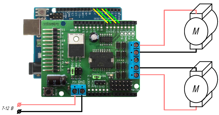
Let's assemble a circuit of two engines:
Let's create a class MotorClass and add variables to it for the current state of the motor (speed and direction of rotation). In addition, we will create variables that will be used when changing speed smoothly
Our class will have several methods:
MotorClass(pE, pI) – class constructor, here we will indicate which outputs we will control the motor
RunMotor(motorpower) – we change internal variables (power, direction) and directly control the motor.
SetSpeed(newspeed) – set a new speed. The power varies in the range of 0..255, which is not always convenient. Therefore, we will set the speed in % of the maximum
SetSpeed(newspeed, smooth) – we set a new speed, we do it not immediately, but smoothly – we set the corresponding variables, and the speed itself will be changed by the function UpdateSpeed()
UpdateSpeed() – here the time interval will be checked and the speed will be changed if the corresponding variables were set by the previous method. We place this function in loop()
Here's what we got:
/* Custom DC motor control class with ramp support */
class MotorClass
{
public:
byte pinE; // Digital output number for speed control - must support PWM
byte pinI; // Digital output number for controlling the direction of rotation

boolean SpeedChanging; // Is engine acceleration mode enabled (handled by the UpdateSpeed() function)
unsigned long StartTimer; // Timer for soft start
int StartTimeStep; // Engine power change interval, in ms
int StartPowerStep; // One step change in engine power
int ReqPower // Up to what value the engine power will change
int Power; // Engine power (0 - stop, 255 - full power)
int Direction; // Direction of rotation


MotorClass(int pE, int pI) // Class constructor. The first argument is the speed control pin number, the second is the direction
{
pinE=pE; // Set control pins for speed
pinI=pI; // And rotation directions
pinMode(pinE, OUTPUT); // Set the operation of the corresponding pins as outputs
pinMode(pinI, OUTPUT);
Power=0; // by default the engine is stopped
SpeedChanging=false; // by default the engine is not accelerated
}
void RunMotor(int motorpower) // Set the speed and direction of rotation of the motor
// Negative value - rotation in the opposite direction
{
Direction=(motorpower>0)?HIGH:LOW; // If a positive speed is specified, a HIGH signal is sent to the direction output
digitalWrite(pinI,Direction); // for negative - LOW
digitalWrite(pinE,abs(Power)); // Apply a signal to the speed control output that corresponds to the desired speed
}
void SetSpeed(int newspeed) // Set the engine speed as a percentage of the maximum.
{
Power=(int)newspeed/2.55; // Since the speed varies from 0 to 100%, and the power ranges from 0 to 255,
// calculate the required power value
RunMotor(Power);
}
void SetSpeed(int newspeed, int smooth) // Smoothly change the engine speed as a percentage of the maximum.
// Negative value - rotation in the opposite direction
// The smoothness of the change is controlled by the smooth value (time per step of speed change, in ms)
{
ReqPower=(int)newspeed/2.55; // Since the speed varies from 0 to 100%, and the power ranges from 0 to 255, we calculate the desired value
if (ReqPower>=Power) // In what direction will the power change?
StartPowerStep=1; // increase by 1 (1/255 of full)
else
StartPowerStep=-1; // decrease by 1 (1/255 of full)
StartTimeStep=smooth;
StartTimer=millis(); // Start counting down the time to change the speed
SpeedChanging=true; // set the speed change mode for subsequent processing in the UpdateSpeed() function
}
void UpdateSpeed()
{
if (SpeedChanging) // If the speed changing mode is set
if ((millis()-StartTimer)>= StartTimeStep) // If more time has passed since the previous speed change than specified
{
if (Power!=ReqPower) // Not yet reached the required speed
{
Power+=StartPowerStep; // change the speed
RunMotor(Power); // give a command to the engine
StartTimer=millis(); // set the timer to start counting for the next power change
}
else // If the required speed is reached
SpeedChanging=false; // Turn off speed change mode
}
}
};
MotorClass M1(5,4); // The first motor is controlled by outputs 5 and 4 (speed and direction respectively)
MotorClass M2(6,7); // The second motor is controlled by outputs 6 and 7

void setup()
{
M1.SetSpeed(50); //First engine - turn on at 50% speed
M1.SetSpeed(-100, 2); // Second engine - turn on 100% speed in the opposite direction with smooth acceleration
}
void loop()
{
M1.UpdateSpeed(); // Handle speed changes of the first motor
M2.UpdateSpeed(); // Handle speed changes of the second motor
}
When the program starts, the first motor will accelerate to half its maximum speed as quickly as possible. But the second one will rotate in the opposite direction, and it will take half a second to accelerate from zero to maximum (255 steps of change in 2ms). The motors are controlled independently, and adding several more motors will not cause any difficulties. On our motor-shield there are no more pins for connecting motors, but nothing prevents us from using two identical ones (the only limitation is that only one can be installed on top of the controller, the second will need to be connected with wires to the corresponding outputs. But for such cases, there are four-channel motor-shields, which use two or more L298P microchips: 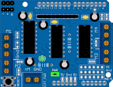
Such a board can already control four DC motors, that is, it is possible, for example, to make completely independent control of each wheel of a four-wheeled robot. The only drawback is that this option uses almost all the digital outputs of a regular UNO board. But this problem can be solved either by using a more functional board (for example, Arduino MEGA with 54 digital outputs) or connecting a motor-shielda via L2P.