Books
Books Technology
 Electronics
 DC motors
 Raspberry Pi Controllers
 Relay
Relay Temperature sensors
 Analog sensors
 Digital sensors
 ADC
ADC Bluetooth
 Radio communication 2.4 GHz
 LCD-screen
 All tags
 Programming
 Web-interface
 Graphical interface
 Windowed Application
 Video
Video Images
 Audio
Audio Text
Text HTML
HTML Lof-files
 Neural networks
 Weaponry
 Projects
Mobile platform for testing electric motors
Mobile platform for testing electric motors. Allows you to control the movement of the platform in real time, which moves along the test route and take parameters from the sensors. One or two DC motors or one stepper motor can be tested on the platform Platform equipped with optical sensor which control movement using black/white stripes on the track The data is transferred to a PC using bluetooth. To process data from sensors and control the system, a separate desktop application is used
Main system parameters:
- Number of tested DC motors - 2
- Number of tested stepper motors - 1
- Rated voltage of motors – 6-13.8 V
- Rated current on the motor - 15A
- Peak current on the motor - 20A
- Engine speed - up to 6000 rpm
- Sensor polling rate - up to 20 polls / sec
- Accuracy of voltage determination - up to 0.054 V
- Accuracy of current determination - up to 0.1 A
- Accuracy of determination of power consumption - up to 0.0054 W
- Accuracy of determining the number of engine revolutions - up to 1/20 of a revolution
- Accuracy of determining the engine speed - up to 15 rpm
- Accuracy of determining platform movements - up to 5 mm
- Accuracy of platform speed determination – up to 50 mm/s
Functions:
- Testing of elecrical motors for different conditions
- Real-time control of different parameters:
- requency of rotation of the motor shaft
- number of revolutions made by it
- voltage
- current
- power consumed by the motor
- linear movement of the platform (based on optical sensor)
- speed of platfrom
- acceleration
- Real time control:
- start or stop any of the engines
- regulate their speed in automatic or manual mode
- control the light indicators on the platform
- Recording a log of sensor readings with an adjustable frequency of up to 20 polls per second.
- Log output both in textual or tabular form, and as a graph
- Ability to save a log of sensor readings in text form for subsequent use in calculations (Excel, mathematical packages MatCAD, MatLab)
- Ability to open previously saved logs.
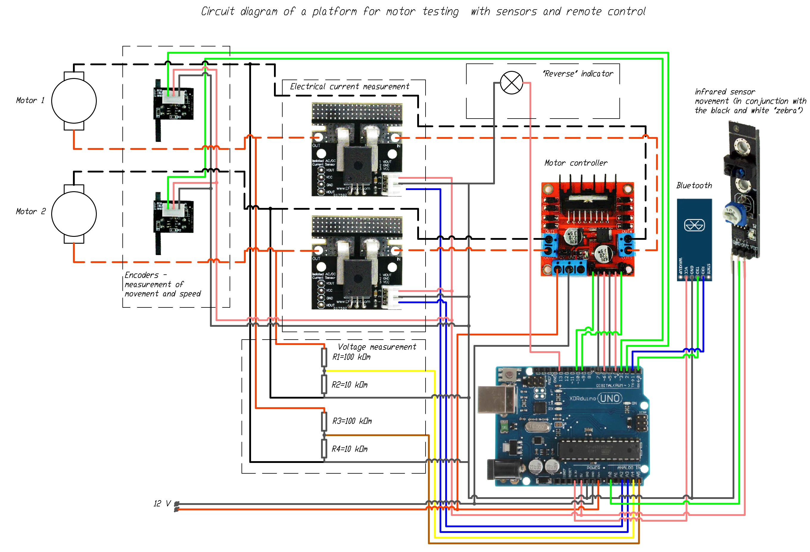
Wiring diagram:
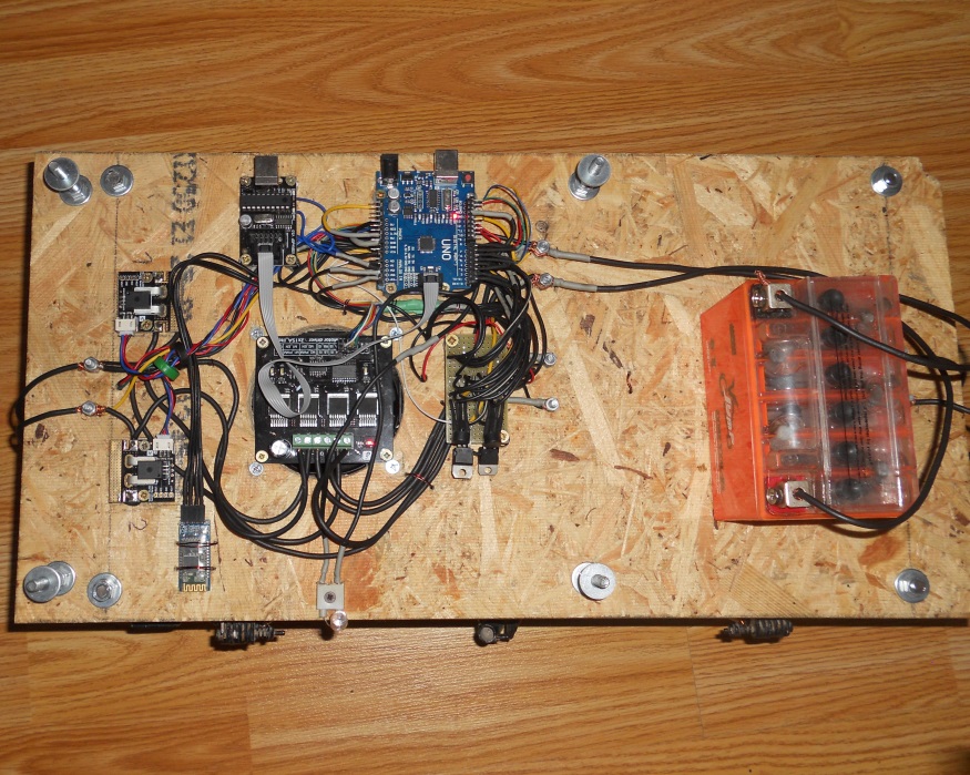
Components:
System contains following components:
- Aduino UNO controller
- Motor controller 2x15A
- Encoders
- Current sensors
- Infrared sensor
- Bluetooth board HC-05 for Arduino
- Bluetooth adapter for computer
- Connectors, wires, connectors, components
Control application
System connected to desktop control application (OS Windows, .Net)
Main functions of control application:
- Real-time output of sensor readings:
- The frequency of rotation of the motor shaft, the number of revolutions made by it;
- Voltage, current and power consumed by the motor
- Linear movement of the platform, its speed and acceleration.
- Platform control:
- start or stop any of the engines
- regulate their speed in automatic or manual mode
- control the light indicators on the platform
- Recording a log of sensor readings with an adjustable frequency of up to 20 polls per second.
- Log output both in textual or tabular form, and as a graph
- Ability to save a log of sensor readings in text form for subsequent use in calculations (Excel, mathematical packages MatCAD, MatLab)
- Ability to open previously saved logs.
Data transferred via bluetooth or wired connection with emulation of COM port
Main view on platform control application: 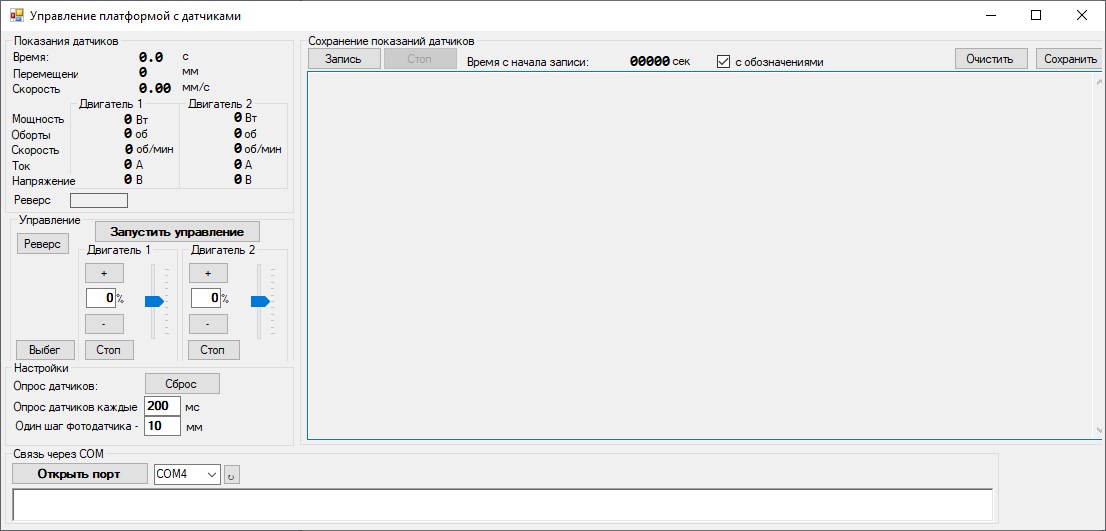
Example of output window during testing: 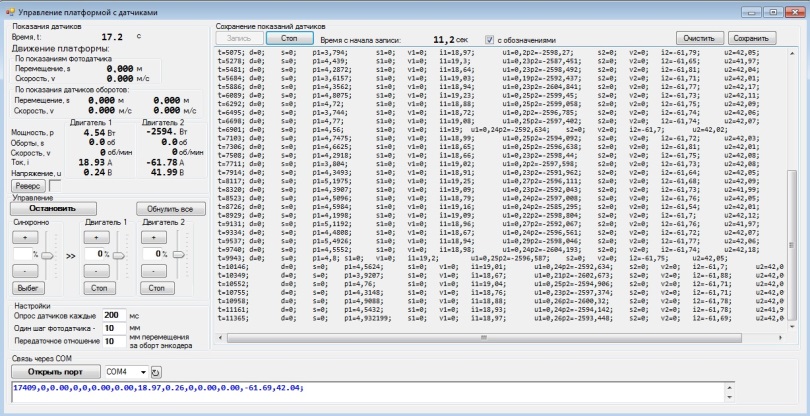
Gallery
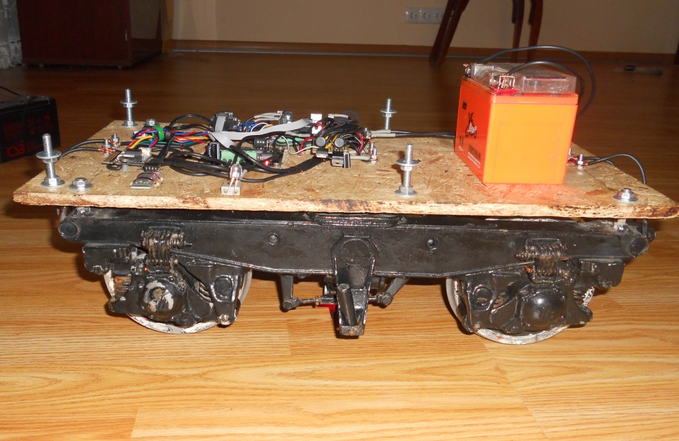
General view on platform: